VOXL 2 Linux User Guide
Table of contents
UARTs
The following is accurate as of System Image 1.3.
Overview
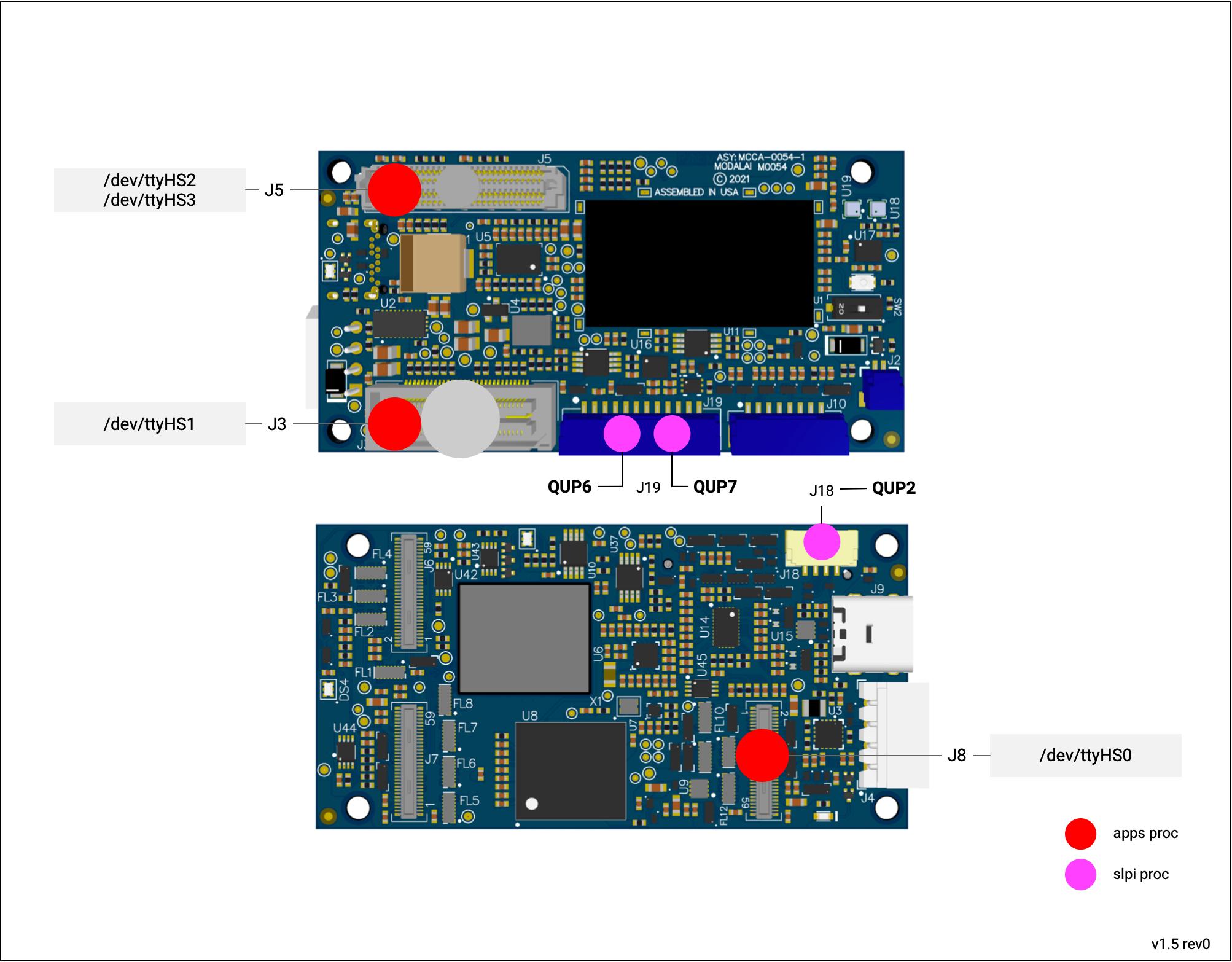
- Note: not shown is ttyHS3 on HS B2B J5
Apps Proc
/dev/ttyHS0 - Camera Group 2 UART
| Device | /dev/ttyHS0 |
| Pins | J8 Pins 38/40 (Tx/Rx) |
| Voltage | 1.8V, directly connected to QRB5165, likely need to level shift |
| Code Sample | TODO |
| Add-Ons | NA |
/dev/ttyHS1 - B2B Connector UART
| Device | /dev/ttyHS1 |
| Pins | J3 Pins 3/5 (Rx/Tx) |
| Voltage | 1.8V, directly connected to QRB5165, likely need to level shift |
| Code Sample | TODO |
| Add-Ons | M0125 - UART/USB3 Add-On, UART7 |
/dev/ttyHS2 - HSB2B Connector UART
| Device | /dev/ttyHS2 |
| Pins | J5 HS B2B pins 48/49 (Rx/Tx) |
| Voltage | 1.8V, directly connected to QRB5165, likely need to level shift |
| Code Sample | TODO |
| M0090 - 5G Add-On Board J9 Pins 2/3 (Tx/Rx) |
/dev/ttyHS3 - HSB2B Connector UART
| Device | /dev/ttyHS3 |
| Pins | J5 HS B2B pins 97/98 (Rx/Tx) |
| Voltage | 1.8V, directly connected to QRB5165, likely need to level shift |
| Code Sample | TODO |
| M0130 - LTE v2 Pro - J8 Pins 10/11 (Tx/Rx) - Level Shifted to 3.3V |
SLPI Proc
QUP2 - ESC UART
| Device | QUP2 |
| Pins | J18 Pins 2/3 (Tx/Rx) |
| Voltage | 3.3V, via directional level shifters |
| Code Sample | PX4 ESC Driver |
| Add-Ons | VOXL ESC |
QUP6 - GNSS UART
| Device | QUP6 |
| Pins | J19 Pins 2/3 (Tx/Rx) |
| Voltage | 3.3V, via directional level shifters |
| Code Sample | PX4 GPS |
| Add-Ons | VOXL 2 GPS Mag Assembly |
QUP7 - RCIO UART
| Device | QUP7 |
| Pins | J19 Pins 10/11 (Tx/Rx) |
| Voltage | 3.3V, via directional level shifters |
| Code Sample | PX4 px4io Driver |
| PX4 RC Driver | |
| Add-Ons | VOXL 2 IO |
| VOXL 2 GPS Mag Assembly |
SPI
The following is accurate as of System Image 1.3.
Overview
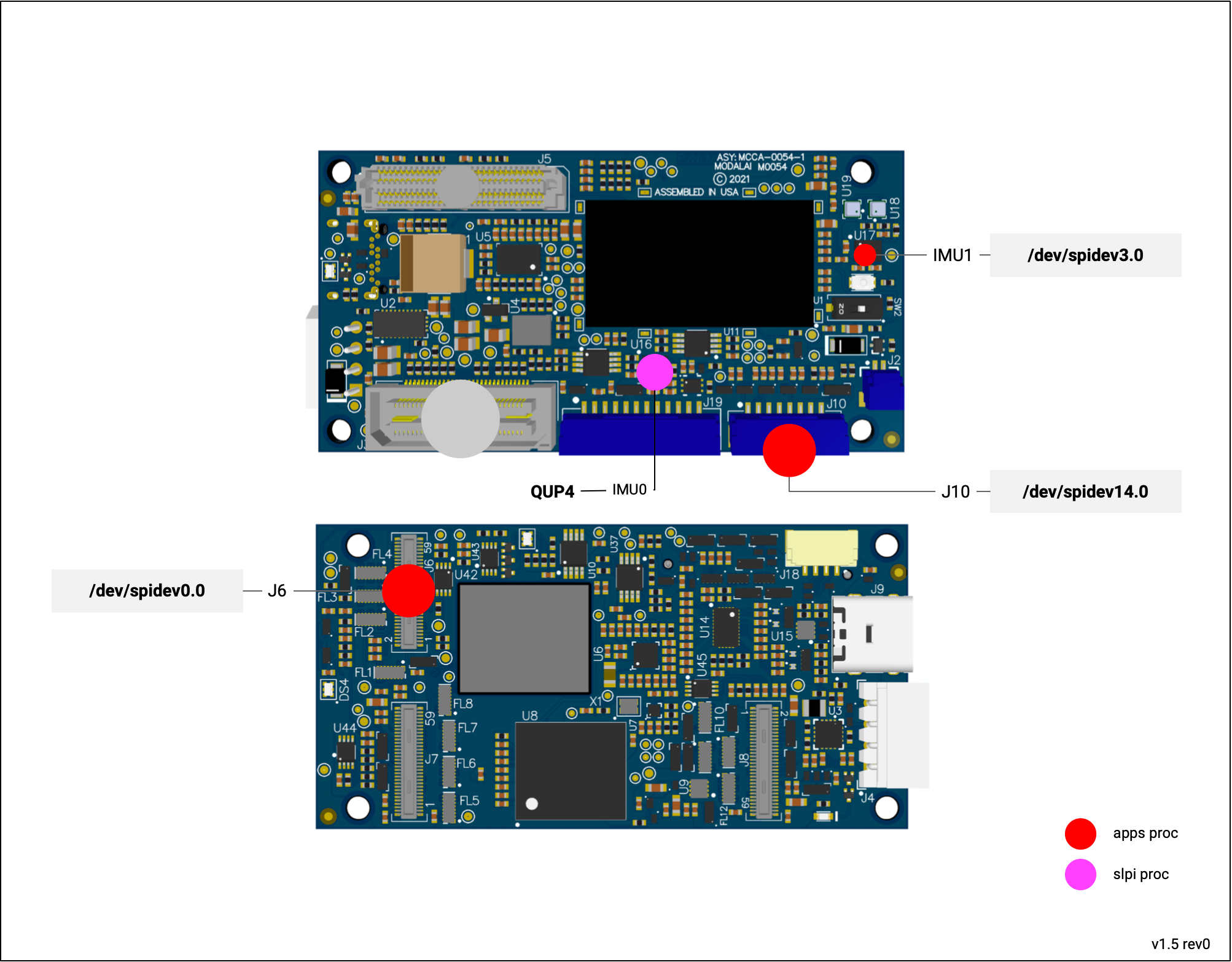
- Note: not shown is spidev11 on HS B2B J5
/dev/spidev0.0  --> camera group 0 (J6)
/dev/spidev3.0  --> internal IMU (TDK ICM-42688p)
/dev/spidev11.0 --> HS B2B connector (J5)
/dev/spidev14.0 --> external SPI (J10)
Apps Proc
SPI0 - Camera Group 0 SPI
| Device | /dev/spidev0.0 |
| Code Sample | VOXL SDK IMU Server |
| Voltage | 1.8V, directly connected to QRB5165, likely need to level shift |
| Pins | J6 - 34 MISO |
| J6 - 36 MOSI | |
| J6 - 38 SCLK | |
| J6 - 40 CS_N |
SPI3 - IMU1
| Device | /dev/spidev3.0, exposed in MPA as /run/mpa/imu_apps |
| Code Sample | VOXL SDK IMU Server |
| Voltage | Internal |
| Pins | U17 - 1 MISO |
| U17 - 14 MOSI | |
| U17 - 13 SCLK | |
| U17 - 12 CS_N |
SPI11 - J5 B2B SPI
Available in system image 1.5+
| Device | /dev/spidev11.0 |
| Code Sample | VOXL SDK IMU Server |
| Voltage | 3.3VDC |
| Pins | J5 - 53 MISO |
| J5 - 54 MOSI | |
| J5 - 55 SCLK | |
| J5 - 56 CS_N |
Available from M0130 addon - J8 pin 2-5
SPI14 - J10 External SPI
| Device | /dev/spidev14.0 |
| Code Sample | VOXL SDK IMU Server |
| Voltage | 3.3VDC |
| Pins | J10 - 2 MISO |
| J10 - 3 MOSI | |
| J10 - 4 SCLK | |
| J10 - 5 CS_N |
Available from J10 pins 2-5
SLPI Proc
QUP5 - IMU0
| Device | exposed via MAP at /run/mpa/imu_px4 |
| Code Sample | VOXL SDK IMU Server |
| Voltage | Internal |
| Pins | U16 - 1 MISO |
| U16 - 14 MOSI | |
| U16 - 13 SCLK | |
| U16 - 12 CS_N |
I2Cs
The following is accurate as of System Image 1.3.
Overview
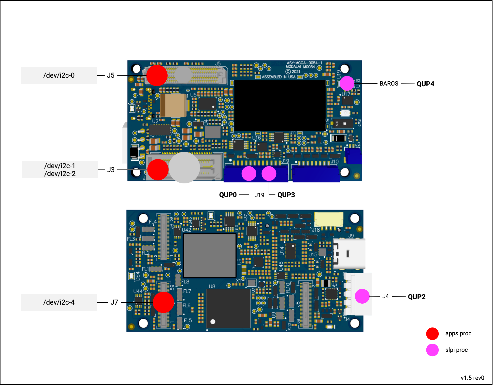
Apps Proc
i2c-0 - I2C2 - HS B2B I2C
/dev/i2c-0 is exposed on the HS B2B connector (J5) pins 8/9.
| Device | /dev/i2c-0 (new as of system image 1.5) |
| Code Sample | |
| Voltage | 3.3VDC |
| Pins | J5 Pin 8/9 (SDA/SCL) (GPIO 115/116) |
| Add-Ons | M0130 J8 Pins 8/9 (SDA/SCL) |
i2c-1 - I2C9 - B2B I2C - GPIO 125-126
/dev/i2c-1
| Device | /dev/i2c-1 (as of system image 1.5, was i2c-0 before) |
| Code Sample | |
| Voltage | 3.3VDC |
| Pins | J3 Pin 13/15 (SCL/SDA) (GPIO 126/125) |
i2c-2 - I2C10 - B2B I2C - GPIO 129-130
/dev/i2c-2 is exposed on the Legacy B2B connector’s pins 23 and 25, and available on add-on boards via a JST connector.
| Device | /dev/i2c-2 (as of system image 1.5, was i2c-1 before) |
| Code Sample | |
| Voltage | 3.3VDC |
| Connector | M0054 J3 Pins 23/25 (SCL/SDA) (GPIO 130/129) |
| Add-Ons | M0062 J9 Pins 4/5 (SDA/SCL) |
| M0090 J9 Pins 4/5 (SDA/SCL) |
i2c-3 - I2C15 - USB Redriver (internal, don’t use)
Status: dmesg shows some errors, need to investigate
| Device | /dev/i2c-3 (as of system image 1.5, was i2c-2 before) |
| Hardware | PN NB7VPQ904MMUTWG datasheet |
| Address: 0x1C |
i2c-4 - I2C1 - Camera Group 1 I2C
/dev/i2c-4 is exposed on the J7 camera group connector
| Device | /dev/i2c-4 |
| Code Sample | |
| Voltage | 1.8VDC |
| Connector | M0054 J7 Pins 34/36 (SCL/SDA) (GPIO 4/5) |
SLPI Proc
QUP0 - External Sensor (Magnetometer)
Typically used for magnetometer I2C connection.
| ID | QUP0 |
| Code Sample | |
| Voltage | 3.3VDC |
| Pins | J19 Pins 4/5 (SCL/SDA) |
| Add-Ons | VOXL 2 GPS Mag Assembly |
QUP2 - External Sensor (Power Monitoring)
Typically used for battery power monitoring I2C connection.
| ID | QUP2 |
| Code Sample | |
| Voltage | 5.0VDC |
| Pins | J4 Pins 3/4 (SCL/SDA) |
| Add-Ons | VOXL PMv3 |
QUP3
Future use.
| ID | QUP3 |
| Code Sample | |
| Voltage | 3.3VDC |
| Pins | J19 Pins 7/8 (SCL/SDA) |
| Add-Ons | NA |
QUP4 - Internal Sensors (Barometers)
Connected to onboard barometers.
| ID | QUP4 |
| Code Sample | |
| Hardware | TDK-ICP10100 @ 0x63h |
| bmp388 @ 0x76h |
GPIOs
The following is accurate as of System Image 1.3.
Apps Proc
Work in progress to expose more GPIOS:
VOXL SDK - voxl-bind source code example.
J3 - B2B
See changelog for version info.
| GPIO | Direction | Description |
|---|---|---|
| 52 | In | J3 Pin 7, pulldown - exposed by M0090, M0062 - J8 pin 2 at 3P3V |
| 53 | Out | J3 Pin 9, default high, 1P8V - exposed by M0090, M0062 - J8 pin 3 at 3P3V (for M0048 pDDL_EN_N) |
| 54 | Out | J3 Pin 19, default low, 1P8V - exposed by M0090, M0062 - J8 pin 4 at 3P3V |
| 55 | Out | J3 Pin 17, default low, 1P8V - exposed by M0090, M0062 - J8 pin 5 at 3P3V |
| 131 | Out | J3 Pin 38 - default low, 1P8V |
| 124 | Out | J3 Pin 40 - default high,1P8V |
J5 - HS B2B
See changelog for version info.
| GPIO | Direction | Description |
|---|---|---|
| 0 | In/Out | J5 Pin 46, default high, 1P8V |
| 1 | In/Out | J5 Pin 47, default high, 1P8V |
| 56 | In/Out | J5 Pin 50, default high, 1P8V |
| 57 | In/Out | J5 Pin 51, default high, 1P8V |
| 89 | In/Out | J5 Pin 79, default high, 1P8V - for M0130, controls whether interface on J8 is SPI (default) or UART (DT change needed to convert) |
| 152 | In/Out | J5 Pin 44, default high, 1P8V |
| 153 | In/Out | J5 Pin 43, default low, 1P8V |
| 154 | In/Out | J5 Pin 42, default low, 1P8V |
| 155 | In/Out | J5 Pin 41, default low, 1P8V |
J6
Note: As of system image 1.5:
| GPIO | Direction | Description |
|---|---|---|
| 113 | In/Out | J6 - 16, exposed though interposer M0076 TP2 |
| 110 | In/Out | J6 - 18, exposed though interposer M0076 TP3. Note: camera HW ID 1 reset |
J7
Note: As of system image 1.5:
| GPIO | Direction | Description |
|---|---|---|
| 6 | In/Out | J7 - 38, exposed though interposer M0076 TP7 |
| 7 | In/Out | J7 - 40, exposed though interposer M0076 TP8 |
J8
Note: As of system image 1.5:
| GPIO | Direction | Description |
|---|---|---|
| 12 | In/Out | J8 - 34, exposed though interposer M0076 TP5 |
| 13 | In/Out | J8 - 36, exposed though interposer M0076 TP6 |
J10
| GPIO | Direction | Description |
|---|---|---|
| 46 | Out | J10 Pin 6 (SPI4 CS1, used for Spektrum bind) |
LEDs
| GPIO | Direction | Description |
|---|---|---|
| 82 | Out | DS2 LED, Red |
| 83 | Out | DS2 LED, Green |
| 84 | Out | DS2 LED, Blue |
Regulators
| GPIO | Direction | Description |
|---|---|---|
| 157 | Out | Controls U41, the 5V/2A switchable power supply for USB |
| 159 | Out | Controls U24, the 3.3VDC supply for RC / VOXL2 IO, J19 pin 9 |
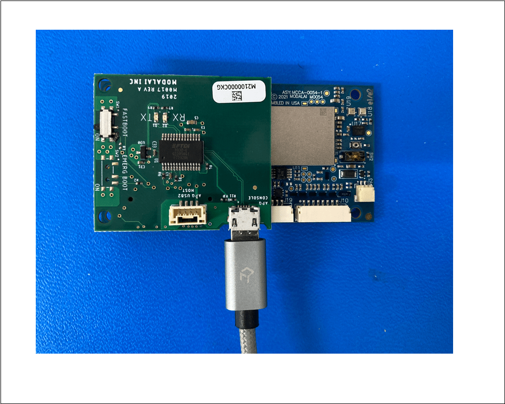
Serial Debug Console
This is enabled in DEBUG builds of the system image and not enabled by default.
You can access via:
- M0017
APQ Console.
- M0062 J6.
Running the following after power on, for example:
screen /dev/tty.usbserial-AU03BMG9 115200
Watch the booting progress:
[  OK  ] Stopped Modem Init Service.
[  OK  ] Started Modem Init Service.
[  OK  ] Stopped Modem Init Service.
[FAILED] Failed to start Modem Init Service.
See 'systemctl status init_sys_mss.service' for details.
[  OK  ] Started depends update.

Ubuntu 18.04.5 LTS qrb5165-rb5 ttyMSM0

qrb5165-rb5 login: