Flight Core Connectors
Table of contents
- Board Connections and Pin-out Specifications
- J1 - VOXL Communications Interface Connector
- J2 - Programming and Debug Console
- J3 - USB Connector
- J4 - UART ESC, UART2/TELEM3
- J5 - Telemetry Connector
- J6 - VOXL-Power Management Input / Expansion
- J7 - 8-Channel PWM Output Connector for PWM or DShot ESCs
- J8 - CAN Bus Connector
- J9 - PPM RC In
- J10 - External GPS & Magnetometer Connector
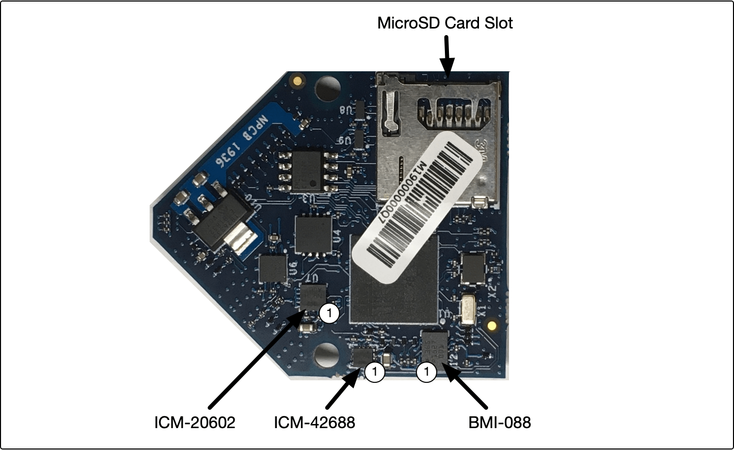
- J11 - MicroSD
- J12 - RC input / USART6 Connector
- J13 - I2C Display / I2C2 Bus / Safety Switch Connector
Board Connections and Pin-out Specifications
Note: Due to supply chain issues, the colors of the connectors on Flight Core are subject to change. If the colors of the connectors on your flight core are different, please disregard.
Flight Core Board Top
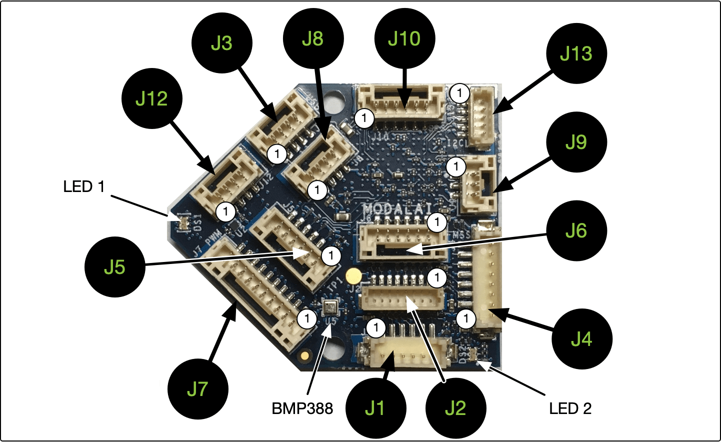
| Connector | Summary |
|---|---|
| J1 | VOXL Communications Interface Connector (TELEM2, /dev/ttyS4, UART5) |
| J2 | Programming and Debug Connector |
| J3 | USB Connector |
| J4 | UART ESC, (UART2, /dev/ttyS1, TELEM3 |
| J5 | Telemetry Connector (TELEM1, /dev/ttyS6, UART7) |
| J6 | VOXL-Power Management Input / Expansion |
| J7 | 8-Channel PWM Output Connector (PWM or DShot ESCs) |
| J8 | CAN Bus Connector |
| J9 | PPM RC In |
| J10 | External GPS & Magnetometer Connector (/dev/ttyS0, UART1) |
| J12 | RC Input, Spektrum/SBus/UART Connector |
| J13 | I2C Display (Spare Sensor Connector) / Safety Button Input |
Flight Core Board Bottom
J1 - VOXL Communications Interface Connector
Connector: 6 Position HIROSE DF13, Vertical, DF13-6P-1.25V(50)
Notes: UART lines are 5V inputs (level shifted to 3.3V by the Flight Core)
| Pin # | Signal Name |
|---|---|
| 1 | 5VDC (input or output if supplied at another pin) |
| 2 | UART_4W_RX_5V |
| 3 | UART_4W_TX_5V |
| 4 | UART_4W_RTS_5V |
| 5 | GND |
| 6 | UART_4W_CTS_5V |
J2 - Programming and Debug Console
Connector: 8 Position, Vertical, BM08B-SRSS-TB(LF)(SN)
Note: used for PX4 debug console, can be used for STM32 FW update
| Pin # | Signal Name |
|---|---|
| 1 | VREG_3V3 |
| 2 | UART_2W_DEBUG_TX |
| 3 | UART_2W_DEBUG_RX |
| 4 | SWDIO |
| 5 | SWCLK |
| 6 | GND |
| 7 | !RESET |
| 8 | VPP_STM |
J3 - USB Connector
NOTE: This connector does not provide system power
Connector: 4 Position JST GH, Vertical, BM04B-GHS-TBT
| Pin # | Signal Name |
|---|---|
| 1 | VBUS_IN |
| 2 | DATA_M |
| 3 | DATA_P |
| 4 | GND |
J4 - UART ESC, UART2/TELEM3
Connector: 8 Position HIROSE DF13, Vertical, DF13-8P-1.25V(50)
| Pin # | Signal Name |
|---|---|
| 1 | 5VDC (other pins are 3.3V, input or output if supplied at another pin) |
| 2 | UART_4W_RX_3V3 |
| 3 | UART_4W_TX_3V3 |
| 4 | UART_4W_RTS_3V3 |
| 5 | GND |
| 6 | UART_4W_CTS_3V3 |
| 7 | GPIO (MSS Status Output) |
| 8 | GPIO (MSS Status Input) |
J5 - Telemetry Connector
Connector: 6 Position JST GH, Vertical, MB06B-GHS-TBT
| Pin # | Signal Name |
|---|---|
| 1 | 5VDC (other pins 3.3V, input or output if supplied at another pin) |
| 2 | UART_4W_TX_3V3 |
| 3 | UART_4W_RX_3V3 |
| 4 | UART_4W_CTS_3V3 |
| 5 | UART_4W_RTS_3V3 |
| 6 | GND |
J6 - VOXL-Power Management Input / Expansion
Connector: 6 Position JST GH, Vertical, BM06B-GHS-TBT
| Pin # | Signal Name |
|---|---|
| 1 | 5VDC (other pins 3.3V, input or output if supplied at another pin) |
| 2 | UART_2W_TX_3V3 |
| 3 | UART_2W_RX_3V3 |
| 4 | EXP_I2C_SCL |
| 5 | EXP_I2C_SDA |
| 6 | GND |
J7 - 8-Channel PWM Output Connector for PWM or DShot ESCs
Connector: 10 Position JST GH, Vertical, BM10B-GHS-TBT
Notes: 5V is for Ref Only
| Pin # | Signal Name |
|---|---|
| 1 | 5VDC (other pins are 3.3V, input or output if supplied at another pin) |
| 2 | PWM_CH1 |
| 3 | PWM_CH2 |
| 4 | PWM_CH3 |
| 5 | PWM_CH4 |
| 6 | PWM_CH5 |
| 7 | PWM_CH6 |
| 8 | PWM_CH7 |
| 9 | PWM_CH8 |
| 10 | GND |
J8 - CAN Bus Connector
Connector: 4 Position JST GH, Vertical, BM04B-GHS-TBT
| Pin # | Signal Name |
|---|---|
| 1 | 5VDC |
| 2 | CANH* |
| 3 | CANL* |
| 4 | GND |
*CAN signals are compliant with ISO 11898-2:2016 and SAE J2284-1 to SAE J2284-5
J9 - PPM RC In
Connector: 3 Position JST GH, Vertical, BM03B-GHS-TBT
Note: This JST connector is reversed when compared to VOXL Flight, pinouts are still the same
| Pin # | Signal Name |
|---|---|
| 1 | 5VDC (other pins 3.3V, input or output if supplied at another pin) |
| 2 | PPM_IN |
| 3 | GND |
J10 - External GPS & Magnetometer Connector
Connector: 6 Position JST GH, Vertical, BM06B-GHS-TBT
| Pin # | Signal Name |
|---|---|
| 1 | 5VDC (other pins 3.3V, input or output if supplied at another pin) |
| 2 | EXT_GPS_UART_2W_TX |
| 3 | EXT_GPS_UART_2W_RX |
| 4 | EXT_GPS_I2C_SCL |
| 5 | EXT_GPS_I2C_SDA |
| 6 | GND |
Supported GPS Modules
J11 - MicroSD
MicroSD slot. Information about supported cards is here: https://dev.px4.io/v1.9.0/en/log/logging.html#sd-cards
J12 - RC input / USART6 Connector
Connector: 4 Position JST GH, Vertical, BM04B-GHS-TBT
| Pin # | Signal Name |
|---|---|
| 1 | VREG_3V3 (Spektrum Power) |
| 2 | USART6_TX |
| 3 | SPEKTRUM RX (3.3V), SBus RX (3.3V), USART6_RX |
| 4 | GND |
For additional RC configurations, please see Flight Core Radios
J13 - I2C Display / I2C2 Bus / Safety Switch Connector
Connector: 5 Position, Vertical, BM05B-SRSS-TB(LF)(SN)
| Pin # | Signal Name |
|---|---|
| 1 | VREG_3V3 |
| 2 | GND |
| 3 | I2C2_SDA |
| 4 | I2C2_SCL |
| 5 | Safety Switch In (switch should pull high to 3.3V to enable) |