Flight Core v2 Functional Description
Table of contents
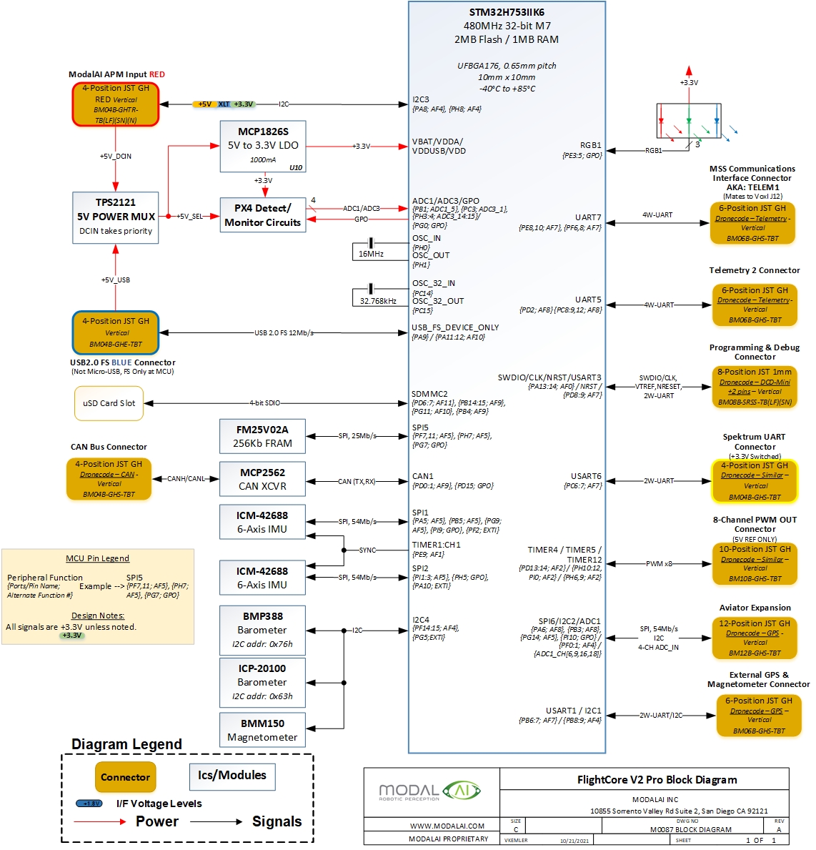
Overview
ModalAI Flight Core v2 is a PX4 flight controller that uses a very similar architecture to FMUv6x. It’s design goal is to be software compatible with the FMUv6x architecture in a smaller Pixracer-style form factor, with an H7 processor.
Changes vs Flight Core v1
- Update to STM32H7 processor (480 MHz vs 216 MHz on v1)
- QTY2 ICM-42688p IMUs
- Added External SPI port, ADC channels
- Added onboard magnetometer (BMM150)
- Additional ICP-20100 baro
- Better alignment with DroneCode connector standards (refer to the connector page) with no more DF13’s (all connectors are JST)
- Dedicated power input – Can now be powered off USB input (see details and limitations below in Power Mux section)
- More robust design – RC input connector is reverse voltage protected (prevents the MCU fusing issue on FCv1 when USB is plugged into Spektrum) – All components are 0402 or larger improving shock resistance and solderability – Sense ADC now includes HW filtering to minimize spurius glitches with Avionics Power monitoring in PX4
Development Kits
| PN | Description |
|---|---|
| MDK-M0087-00 | Flight Core v2 board only |
| MDK-M0087-01 | Flight Core v2 plus: Power Module + Cable (MDK-M0041-1) PWM Breakout Board + Cable (MDK-M0022-1) RC input cable, JST-to-USB-Micro cable, 2x 6pin-JST-to-pigtail break cables |
Dimensions
3D Drawings
2D Drawings
TODO
Features
| Feature | Details |
|---|---|
| Weight | TODO g |
| MCU | 480MHz, 32-bit ARM M7 STM32H753IIK6 |
| Memory | 256Kb FRAM |
| 2MB Flash | |
| 1MB RAM | |
| Firmware | PX4 |
| IMUs | ICM-42688-P (SPI1) |
| ICM-42688-P (SPI2) | |
| External option via SPI6 | |
| Magnetometer | BMM150 (I2C4) |
| Barometers | BMP388 (I2C4) |
| ICP-20100 (I2C4) | |
| Secure Element | A71CH (I2C4) |
| microSD Card | PX4 Supported SD Cards SDHC version 2 up to 32GB |
| Inputs | GPS/Mag |
| Spektrum | |
| Telemetry | |
| CAN bus | |
| Outputs | 3 LEDs (1xRGB) |
| 8 PWM Channels | |
| Extra Interfaces | 2 serial ports |
| I2C | |
| 4CH ADC |
Block Diagram
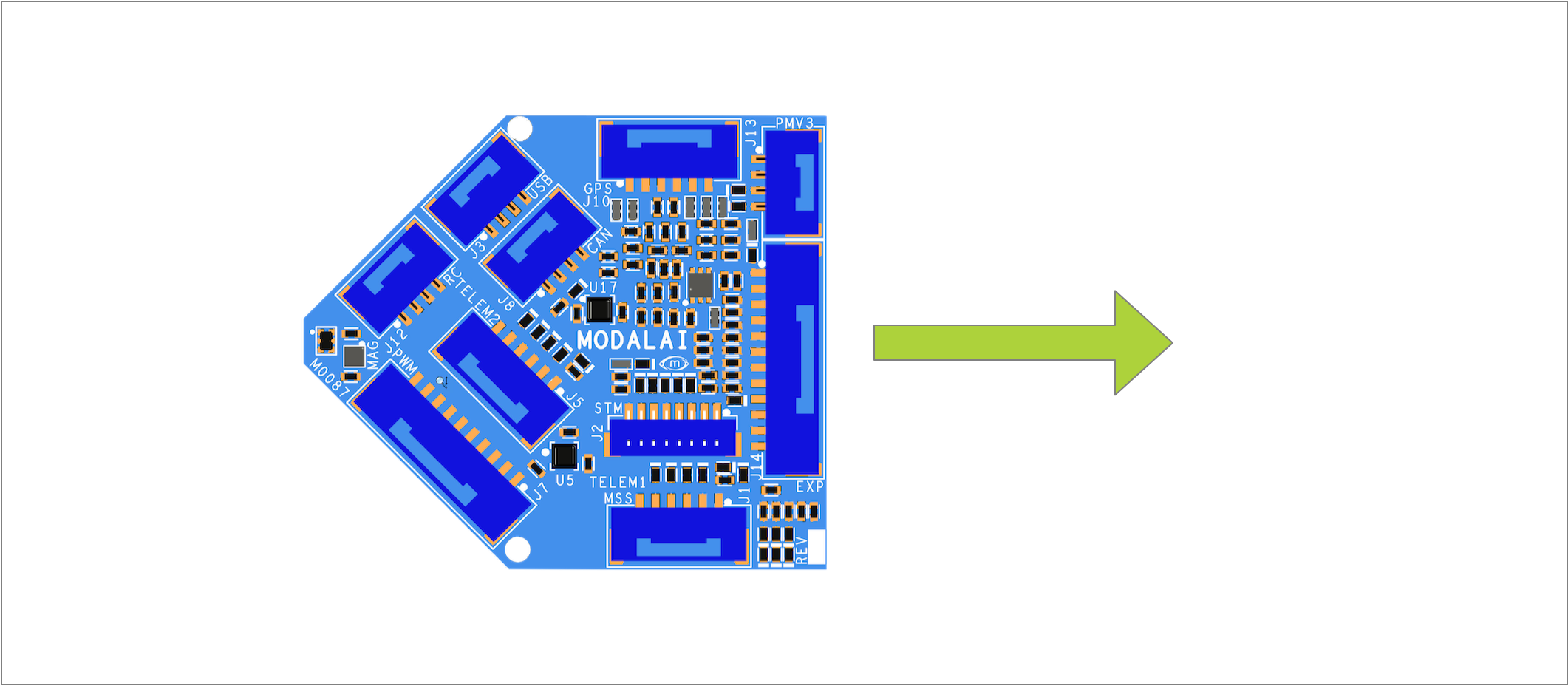
Orientation
The following is a ‘top down’ view of the Flight Core v2 depicting the orientation.
Power Supply and Power Source Mux Details
A 5VDC supply is required to power the Flight Core v2. The VOXL Power Module v3 is recommended, which provides battery voltage and amperage monitoring through an I2C interface when connected to J13 using the TODO cable.
The Flight Core V2 provides a new very convenient powering option for all users. This design incorporates a “Priority Power Mux” as shown here: 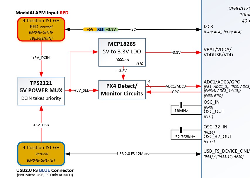
Here is how that mux works:
- 5V Power-in can be applied to either J13 (4-position RED “APM” power in connector) or through the USB host port J3 from a PC (typically running QGC)
- Both power source inputs are validated for 5V present and not over-voltage before being selected as the board power source
- Output power source is set by priority:
- 3a) If the +5V_DCIN is present on J13, this will be selected as the power source no matter what (with or without VBUS present). LED1 will be illuminated GREEN
- 3b) If +5V_DCIN is NOT present, and if VBUS on J3 is valid, the 5V source will be provided by the USB VBUS from the host PC. LED1 will be OFF.
- 3bi) Since VBUS from most PCs is limited to 500mA, it is not recommended to always operate in this mode. When multiple peripherals are installed, like GNSS/MAG + R/C Receivers, etc. it is easy to over-current your USB source and some stuff may start failing or resetting (hence why the LED is OFF in USB mode to maximize ICC availability)
- 3bii) This mode is intended for simple QGC operations like programming, IMU calibration, and limited peripheral connectivity checks without needing to remove your drone’s flight battery and power module. This is not intended to be a flight-mode scenario.
- Power Source switchover:
- 4a) The priority mux has “glitchless” switchover but only in one direction, from VBUS to +5V_DCIN. That is, when powering on the bench via USB, if +5V_DCIN is then applied to J13, the power mux will automatically switch the power source over to J13, and the MCU should not reset.
- 4b) However, if both VBUS and +5V_DCIN are present, and +5V_DCIN is removed, the power mux will revert to VBUS, but it is most likely the MCU will be reset during this switchover event
Thermal Considerations
The STM32H7 family MCU can get hot while running PX4 code since no sleep or low power modes are employed. ModalAI does not provide a default thermal solution for this. We do this because of the following:
- Some customers may not run PX4
- We do not know all customer’s size and weight restrictions/constraints where this board will be installed.
- We would not rather provide a heatsink that you need to remove potentially damaging the MCU or PCB
- If a customer could remove our heatsink without damage, residue on the MCU would likely interfere with your needed thermal pad’s/tape efficacy.
Therefore, we caution every customer to pay attention to the MCU’s thermal output and determine what heatsink/thermal option works best for your aplication. A simple adhesive based passive heatsink or a lightweight low-power fan, much like one we sell, may be the ideal option in most cases. Our 5V output pins on the connectors can easily power such a fan.