Using VOXL ESCs with PX4
Table of contents
Overview
The VOXL 2, VOXL Flight and Flight Core systems provides the ability to easily and quickly interface with UART ESCs. The following guide provides you the necessary details on doing so.
PX4 1.14 and Newer (eg. VOXL2) using Modal IO
The UART ESC / modalai_esc driver was renamed to modal_io starting in 1.14. The modal_io driver is used to interface with the VOXL ESC and can be configured using the QGroundControl Actuators tab or manually using the command line on target.
The driver is located at src/drivers/actuators/modal_io.
Actuator Setup using QGC
Example Screen Shot with Labels
WARNING - we’ve not yet seen the “Indentify & Assign Motors” work with any flight controller at the time of this writing so please do not rely on using this.
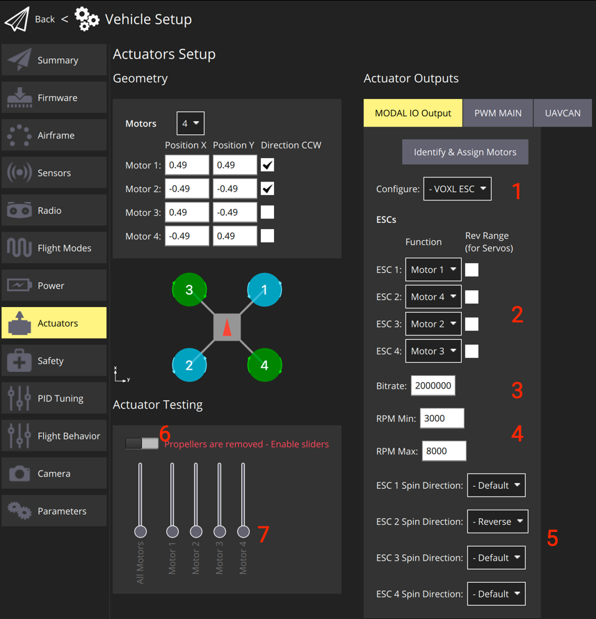
Instructions using QGC
- Click on the Actuators tab
- In the Configure drop down (#1 in graphic above), select
VOXL ESC- reboot the vehicle
- Inspect the wiring of your ESC to motors, e.g.:
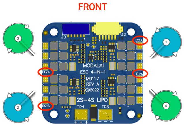
- Use this for configuring the ESC Function (#2 in graphic). Note the silkscreen is 0 based… In the following example we have:
- silksreen ID0 –> ESC 1 –> wired to PX4 motor 1 –>
ESC 1 = Motor 1 - silksreen ID1 –> ESC 2 –> wired to PX4 motor 4 –>
ESC 2 = Motor 4 - silksreen ID2 –> ESC 3 –> wired to PX4 motor 2 –>
ESC 3 = Motor 2 - silksreen ID3 –> ESC 4 –> wired to PX4 motor 3 –>
ESC 4 = Motor 3
- silksreen ID0 –> ESC 1 –> wired to PX4 motor 1 –>
- Do not use “Rev Range” option
- Configure the Bitrate if needed (#3). For VOXL2, the default is
2000000, for FCv1/v2, use250000. - Configure the RPM Min and RPM Max based on your motor selection
- Using the Actuator Testing section, you can enable using a slider (#6) and use the motor sliders (#7) to spin the motors manually
- Note: currently VOXL2 needs to use command line for this
- If needed, change the ESC Spin Direction for a given ESC ID (#8)
Actuator Setup Using Command Line
- Configure mapping using
MODAL_IO_FUNCXparams, where:- Motor 1 =
101 - Motor 2 =
102 - Motor 3 =
103 - Motor 4 =
104
- Motor 1 =
- In the above example, we’d have:
MODAL_IO_CONFIG = 1
MODAL_IO_MODE = 0
MODAL_IO_FUNC1 = 101
MODAL_IO_FUNC2 = 104
MODAL_IO_FUNC3 = 102
MODAL_IO_FUNC4 = 103
MODAL_IO_SDIR1 = 0
MODAL_IO_SDIR2 = 0
MODAL_IO_SDIR3 = 1
MODAL_IO_SDIR4 = 0
MODAL_IO_RPM_MAX = 8000
MODAL_IO_RPM_MIN = 3000
Actuator Testing Using Command Line
To spin motor 1 at 10% for 1 second, the following command can be used, in which we’d expect the front right motor to spin:
actuator_test -m 1 -v 0.1 -t 1
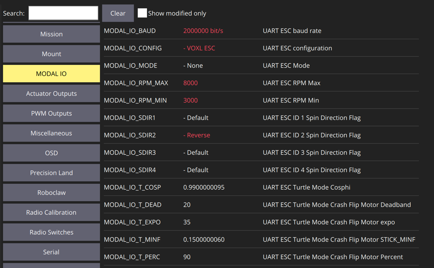
PX4 Params (1.14 and newer)
The following are the PX4 parameters that are used by the modal_io driver:
| Name | Description | Min > Max (Incr.) | Default | Units |
|---|---|---|---|---|
MODAL_IO_CONFIG | UART ESC Configuration Values: - 0: Disabled - 1: VOXL ESC Reboot Required | 0 (Disabled) | ||
MODAL_IO_BAUD | Baud rate between FlightController and Actuator | (1) | 250000 | Bits/sec |
MODAL_IO_FUNC1 | info | 0, 101-104 | 0 | |
MODAL_IO_FUNC2 | info | 0, 101-104 | 0 | |
MODAL_IO_FUNC3 | info | 0, 101-104 | 0 | |
MODAL_IO_FUNC4 | info | 0, 101-104 | 0 | |
MODAL_IO_SDIR1 | Reverse spin direction of ESC ID 0 | 0 > 1 | 0 | |
MODAL_IO_SDIR2 | Reverse spin direction of ESC ID 1 | 0 > 1 | 0 | |
MODAL_IO_SDIR3 | Reverse spin direction of ESC ID 2 | 0 > 1 | 0 | |
MODAL_IO_SDIR4 | Reverse spin direction of ESC ID 3 | 0 > 1 | 0 | |
MODAL_IO_RPM_MAX | Maximum RPM, used by actuator output to determine thrust fullscale. | (1) | 15000 | RPM |
MODAL_IO_RPM_MIN | Minimum RPM, used by actuator output to determine thrust fullscale. | (1) | 5500 | RPM |
The following are use to control “Turtle Mode” (flip over after crash, which is currently in test):
| Name | Description | Min > Max (Incr.) | Default | Units |
|---|---|---|---|---|
MODAL_IO_MODE | UART ESC Mode: Values: - 0: None - 1: Turtle Mode enabled via AUX1 - 2: Turtle Mode enabled via AUX2 Reboot Required | 0 > 2 | 0 | |
MODAL_IO_T_PERC | Turtle Mode Crash Flip Motor Percent (percentage of motor range to use in flip over mode) | 1 > 100 (1) | 90 | Percentage (as int) |
MODAL_IO_T_DEAD | Percentage of fullscale RPM that is in a deadband when in Turtle mode | 1 > 100 (1) | 20 | Percentage (as int) |
MODAL_IO_T_MINF | Minimum stick percentage in the dead zone needed to move | 0.0 > 1.00 (0.01) | 0.15 | Percentage (as float) |
MODAL_IO_T_EXPO | Flip power expo value | 1 > 100 (1) | 35 | Percentage (as int) |
MODAL_IO_COSPHI | Value used to specify the sensitivity for isolating a single motor for spinning | 0.000 > 1.000 (0.001) | 0.990 | Percentage (as float) |
PX4 1.13 and Older
Overview
NOTE! This feature is currently in developer preview and requires you to load the PX4 FW from a branch
- VOXL Flight or Flight Core with this branch
- Note: this is scheduled to release with PX4 v1.12
- A ModalAI UART ESC VOXL ESC v2, PN: MDK-M0049-1-01 - 4-in-1 UART ESC (gen2)
- UART ESC Serial Cable MCBL-00013-1
Video Tutorial
For those of you who prefer videos, we have a video tutorial here that covers the software configuration and usage. Note, you’ll want to look at the hardware connections below as that part is skipped in this video.
TL;DR
Hardware Connections
The guide here describes the connectivity: VOXL ESC v2 Manual
PX4 Setup (1.13 and older)
Enable UART ESC
To enable the UART ESC feature, set the UART_ESC_CONFIG parameter to a value of 1 and power cycle the vehicle.
You can use QGroundControl’s Parameter feature to query and modify the UART_ESC params.
The remainder of the settings can be left as default if you followed the hardware connections described in the previous section.
TELEM3
The UART ESC uses /dev/ttyS1, same as TELEM3. On bootup, if any MAVLink instance is configured to use TELEM3, it will be disabled via boards/modalai/fc-v1/init/rc.board_defaults.
PX4 Params (1.13 and older)
See the section above for 1.14, replacing MODAL_IO prefeix with UART_ESC, for example MODAL_IO_CONFG in 1.13 and older is UART_ESC_CONFIG.
RGB LED Codes
This is currently a work in progress. The standard LED codes should output to the all the LED channels in a similar way as other PX4 RGB LED peripherals with the exception that the breathing pattern is replaced by a fast blink.
Debugging Tips
Setting Up PX4 Motor ID to UART_ESC_MOTORX
Say you have the following:
M0049 silkscreen ID0 channel –> wired to a motor at PX4 Motor ID 2 M0049 silkscreen ID1 channel –> wired to a motor at PX4 Motor ID 3 M0049 silkscreen ID2 channel –> wired to a motor at PX4 Motor ID 1 M0049 silkscreen ID3 channel –> wired to a motor at PX4 Motor ID 4
Then you would have the following params set:
UART_ESC_MOTOR1 = 2 UART_ESC_MOTOR2 = 3 UART_ESC_MOTOR3 = 1 UART_ESC_MOTOR4 = 4
And you can test by spinning, for example, 1000 RPM for 64 command cycles:
# spin PX4 motor #1
modalai_esc -i 1 -r 1000 -n 64 rpm

# spin PX4 motor #2
modalai_esc -i 2 -r 1000 -n 64 rpm

# spin PX4 motor #3
modalai_esc -i 4 -r 1000 -n 64 rpm

# spin PX4 motor #4
Development
The PX4 Driver source code can be found on github