Configure Extrinsics
/etc/modalai/extrinsics.conf is a json file that describes the intrinsics between the coordinate frames of critical components of the drone body. This file can be read using the library libvoxl_common_config.so and the voxl-configure-extrinsics tools, both of which are provided by the voxl-mpa-tools package.
This document serves to describe how to use and configure this file if needed for a custom application. The relation between camera, imu, and drone body (center of mass) is critical for proper VIO function. voxl-inspect-extrinsics is a helpful tool to determine what has been configured.
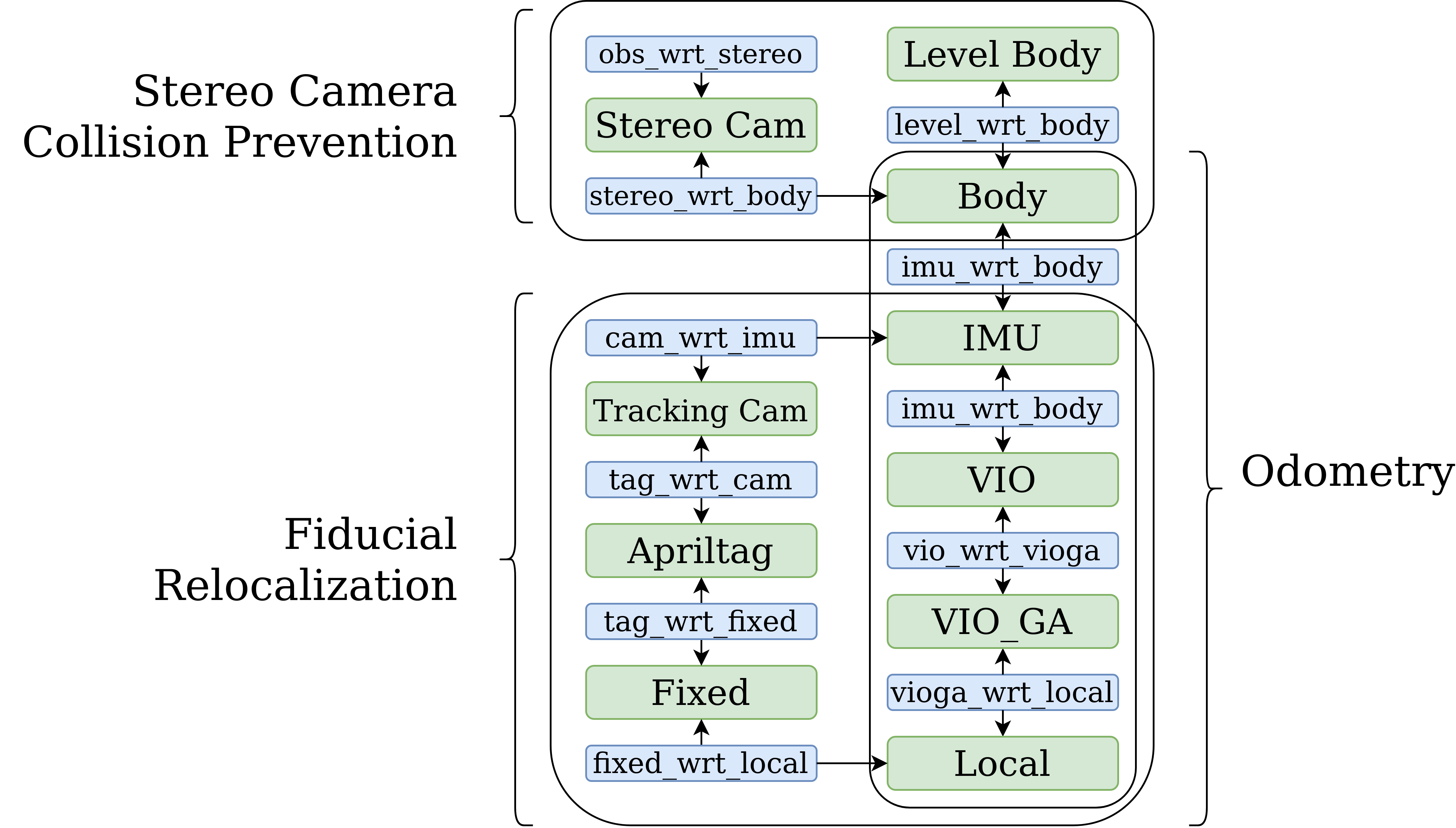
An overview of the coordinate frames used in the extrinsics config file and throughout VOXL-SDK:
Preset Configurations with voxl-configure-extrinsics
The voxl-configure-extrinsics utility will allow you to use preset extrinsics config files or select your own file.
yocto:/$ voxl-configure-extrinsics -h

Start wizard with prompts:
voxl-configure-extrinsics

Shortcut configuration arguments for scripted setup.
leave_alone doesn't touch the file, it does nothing
other factory options wipe /etc/modalai/extrinsics.conf

factory_custom allows you to specify your own custom file which
will then be copied into /etc/modalai/extrinsics.conf

voxl-configure-extrinsics leave_alone
voxl-configure-extrinsics factory_m500_flight_deck
voxl-configure-extrinsics factory_seeker_v1_voxlcam
voxl-configure-extrinsics factory_starling_v1
voxl-configure-extrinsics custom /xx/yy/my_custom_file.conf

show this help message:
voxl-configure-extrinsics help
Running it without arguments will prompt you with a question on how to proceed as follows:
yocto:/$ voxl-configure-extrinsics
Starting Wizard
which preset extrinsics file would you like to use?
1) leave_alone        3) seeker_v1_voxlcam  5) custom
2) m500_flight_deck   4) starling_v1
#? 2
wiping old extrinsics config file
copying /usr/share/modalai/extrinsic_configs/m500_flight_deck.conf to /etc/modalai/extrinsics.conf
loading and updating file with voxl-inspect-extrinsics -q
done configuring extrinsics
File Structure
This configuration file serves to describe the static relations (translation and rotation) between sensors and bodies on a drone. Mostly importantly it configures the camera-IMU extrinsic relation for use by VIO. However, the user may expand this file to store many more relations if they wish. By consolidating these relations in one file, multiple processes that need this data can all be configured by this one configuration file. Also, copies of this file may be saved which describe particular drone platforms. The defaults describe the VOXL M500 drone reference platform.
The file is constructed as an array of multiple extrinsic entries, each describing the relation from one parent to one child. Nothing stops you from having duplicates but this is not advised.
The rotation is stored in the file as a Tait-Bryan rotation sequence in intrinsic XYZ order in units of degrees. This corresponds to the parent rolling about its X axis, followed by pitching about its new Y axis, and finally yawing around its new Z axis to end up aligned with the child coordinate frame.
The helper read function will read out and populate the associated data struct in both Tait-Bryan and rotation matrix format so the calling process can use either. Helper functions are provided to convert back and forth between the two rotation formats.
Note that we elect to use the intrinsic XYZ rotation in units of degrees for ease of use when doing camera-IMU extrinsic relations in the field. This is not the same order as the aerospace yaw-pitch-roll (ZYX) sequence as used by the rc_math library. However, since the camera Z axis points out the lens, it is helpful for the last step in the rotation sequence to rotate the camera about its lens after first rotating the IMU’s coordinate frame to point in the right direction by Roll and Pitch.
The following online rotation calculator is useful for experimenting with rotation sequences: https://www.andre-gaschler.com/rotationconverter/
The translation vector should represent the location center of the child coordinate frame with respect to the parent coordinate frame in units of meters.
The parent and child name strings should not be longer than 63 characters.
The relation from Body to Ground is a special case where only the Z value is read by voxl-vision-px4 and voxl-qvio-server so that these services know the height of the drone’s center of mass (and tracking camera) above the ground when the drone is sitting on its landing gear ready for takeoff.
IMU locations on VOXL
VOXL1
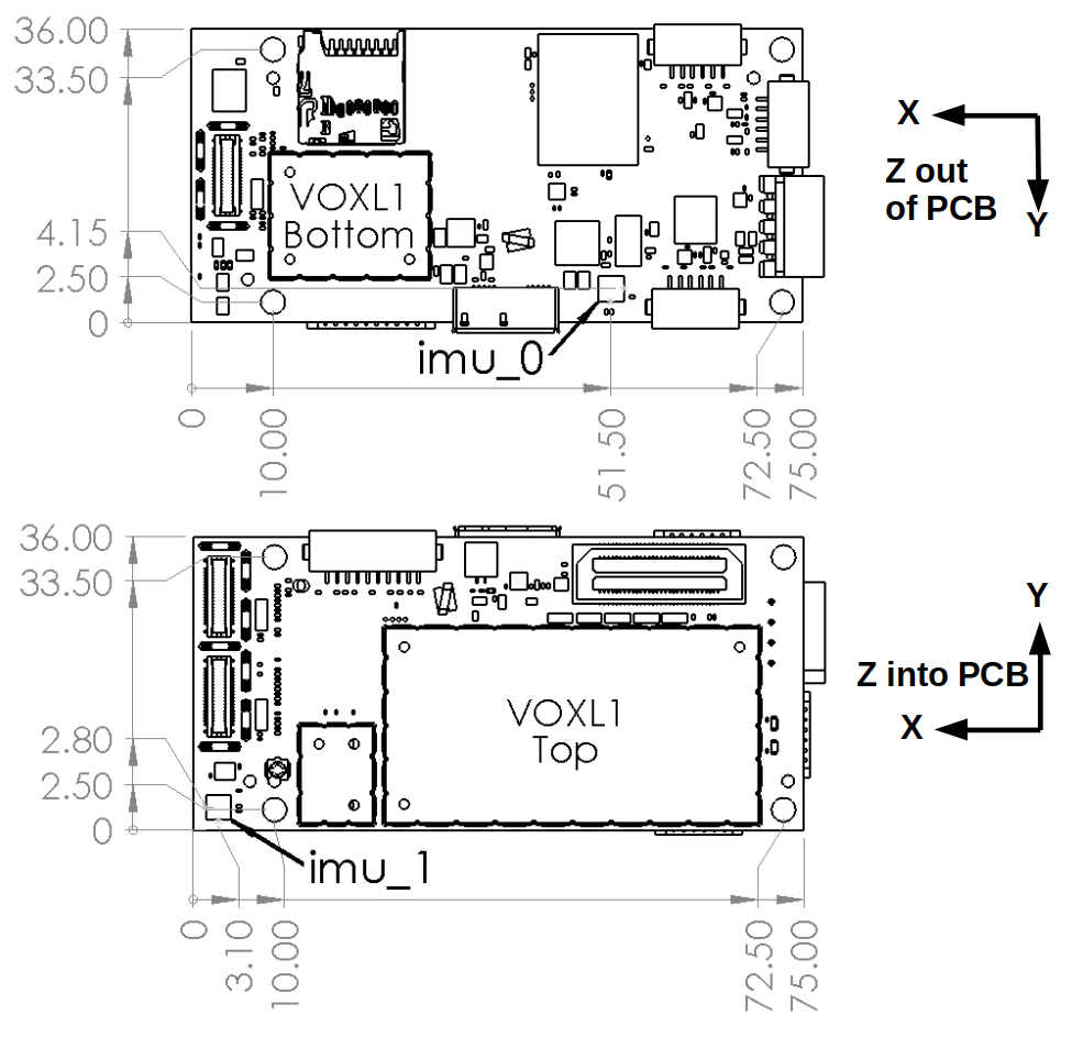
On VOXL1, there are two IMUs: imu1 (primary) and imu0 (secondary). Their locations on the VOXL1 PCB and orientation of published data are as follows:
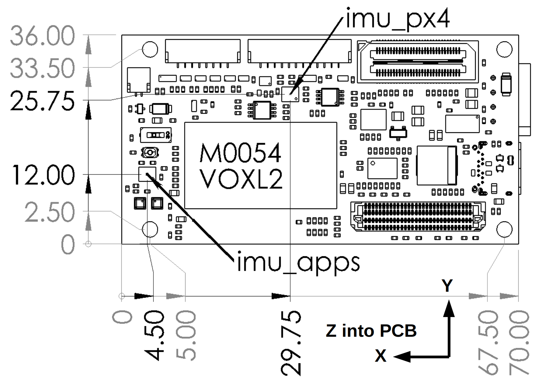
VOXL2
On VOXL2 there are two IMUs: imu_apps is connected to the applications processor and driven by voxl-imu-server to publish IMU data to MPA for VIO and general use. This will publish data
imu_px4 is connected to the SDSP and is driven by PX4 on the SDSP for flight control. Data from imu_px4 is also available in MPA on all QRB5165-based platforms such as VOXL2 and RB5-Flight as long as voxl-px4 and voxl-px4-imu-server are both running. RB5-Flight only has a single IMU (imu_px4) so the data is published in MPA for VIO to use. On VOXL2, imu_apps should be used for VIO.
NOTE that on VOXL1 and VOXL2, voxl-imu-server publishes the IMU data in a common and more useful orientation such that both IMU’s appear to be oriented in FRD frame for the VOXL M500, flight deck, and Starling reference platforms. This common orientation axis are labeled in the above diagrams. You may notice that the default extrinsic files for these platforms have 0 rotation between both IMUs and between the IMU and body frames as a result. While VOXL-SDK supports mounting the VOXL boards in other orientations, it is helpful for reference frames to be consistent where possible, thus we rotate the IMU data in the driver so that IMU data is published consistently across boards regardless of how the IMU is positioned on the PCB.
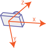
Camera Coordinate Frame
VOXL-SDK uses the standard convention of X to the right, Y down, and Z out the front of the lens. This is the same as OpenCV.
For a camera mounted on the front of a drone facing forward in landscape orientation this would result in:
- The X axis of the camera pointing to the right aligned with the Y axis of the drone.
- The Y axis of the camera pointing down aligned with the Z axis of the drone.
- The Z axis of the camera pointing forward along the X axis of the drone.
Example
Default file for the VOXL M500 and Flight Deck:
{
	"name":	"M500_flight_deck",
	"extrinsics":	[{
			"parent":	"imu1",
			"child":	"imu0",
			"T_child_wrt_parent":	[-0.0484, 0.037, 0.002],
			"RPY_parent_to_child":	[0, 0, 0]
		}, {
			"parent":	"imu0",
			"child":	"tracking",
			"T_child_wrt_parent":	[0.065, -0.014, 0.013],
			"RPY_parent_to_child":	[0, 45, 90]
		}, {
			"parent":	"imu1",
			"child":	"tracking",
			"T_child_wrt_parent":	[0.017, 0.015, 0.013],
			"RPY_parent_to_child":	[0, 45, 90]
		}, {
			"parent":	"body",
			"child":	"imu0",
			"T_child_wrt_parent":	[0.02, 0.014, -0.008],
			"RPY_parent_to_child":	[0, 0, 0]
		}, {
			"parent":	"body",
			"child":	"imu1",
			"T_child_wrt_parent":	[0.068, -0.015, -0.008],
			"RPY_parent_to_child":	[0, 0, 0]
		}, {
			"parent":	"body",
			"child":	"stereo_l",
			"T_child_wrt_parent":	[0.1, -0.04, 0],
			"RPY_parent_to_child":	[0, 90, 90]
		}, {
			"parent":	"body",
			"child":	"tof",
			"T_child_wrt_parent":	[0.1, 0, 0],
			"RPY_parent_to_child":	[0, 90, 90]
		}, {
			"parent":	"body",
			"child":	"ground",
			"T_child_wrt_parent":	[0, 0, 0.1],
			"RPY_parent_to_child":	[0, 0, 0]
		}]
}
Other default files can be set up with voxl-configure-extrinsics and can be viewed here
Let’s deconstruct one of the more critical entries in this file, the relation between the IMU (imu0) and the tracking camera. This is used for VIO and needs to be accurate for VIO to function.
	"parent":	"imu0",
	"child":	"tracking",
	"T_child_wrt_parent":	[0.065, -0.014, 0.013],
	"RPY_parent_to_child":	[0, 45, 90]
From the two sections above, we know that the IMU data is aligned with the drone body frame (FRD Forward Right Down) and the Camera frame uses the same convention as openCV (Right, Down, forward). First we look at the translation.
The translation is the location of the child frame WITH RESPECT TO the parent. Given the vector [0.065, -0.014, 0.013] we can read that as the camera is 65mm in front of, 14mm to the left of, and 13mm below the IMU.
The intrinsic XYZ (RPY) rotation [0, 45, 90] correctly rotates the parent frame to align with the camera frame for the M500 with tracking camera pointing forward and down 45 degrees below the horizon. This can be read as having 0 rotation about the IMU’s X (roll) axis, followed by a 45 degree rotation about Y (pitch) to rotate the IMU’s Z axis up from pointing straight down to pointing out along the Camera’s lens. Finally, a 90 degree yaw rotation about the newly aligned Z axis aligns the X and Y axis.
Stereo Camera Extrinsics
Note that the stereo cameras go through a precise calibration procedure to determine the orientation between them, so only the left stereo camera is provided in the extrinsics config file. The right camera has a specified relation to the left camera in /data/modalai/opencv_stereo_extrinsics.conf which is created by the stereo calibration process.