VOXL ESC Manual
Table of contents
- Software Components
- VOXL ESC Tools
- Hardware Diagrams
- ESC Software Start-up Procedure
- ID Assignment
- ESC Spin Test
- Calibration
- Other Resources
- FAQ
Software Components
| Function | Description | Resource Link |
|---|---|---|
| Bootloader | Provides firmware update capability over UART and ensures integrity of the firmware before executing it | Installed on board during production |
| Firmware | Main software that performs all motor control functionality | Coming soon to developer.modalai.com |
| Firmware Parameters | Parameters that allow user to change behavior of the Firmware without changing the Firmware itself | gitlab |
| VOXL ESC Tools | Tools for testing / tuning ESC using a PC | gitlab |
| PX4 Driver | PX4 driver found on main branch of PX4 Firmware | github |
VOXL ESC Tools
VOXL ESC Tools is a Python software package which allows testing, calibration and diagnostics of ESCs using a PC. The ESC tools consist of two parts:
- voxl-esc-tools-bin : proprietary software (voxl-esc-tools-bin-x.x.x.zip) : download from developer.modalai.com
- voxl-esc-tools : open source software : github link
Installation
Get the tools:
git clone git@gitlab.com:voxl-public/flight-core-px4/voxl-esc.git- Install ESC Tools Binary(NEED TO DOWNLOAD THIS TO GET THE SCRIPT TO RUN):
- Download ESC Tools binary here
- Make your way to Misc. & look for
voxl-esc - Then copy and unzip into local voxl-esc git repo:
cp voxl-esc-tools-bin-x.x.x.zip voxl-esc/tools/cd voxl-esc/toolsunzip voxl-esc-tools-bin-x.x.x.zip
Or you can extract the Voxl-Esc-Tools-bin into tools folder that is inside of Voxl-Esc-Master folder
Install Python libraries:
* sudo addgroup <your_user_name> dialout
* sudo apt-get update
* sudo apt-get -y install apt-utils software-properties-common python-pip python-setuptools
* sudo -H pip install --upgrade pip
* sudo -H pip install --upgrade numpy pyserial
VOXL ESC USB Interface
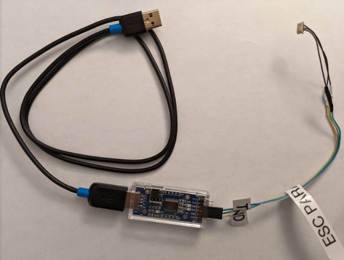
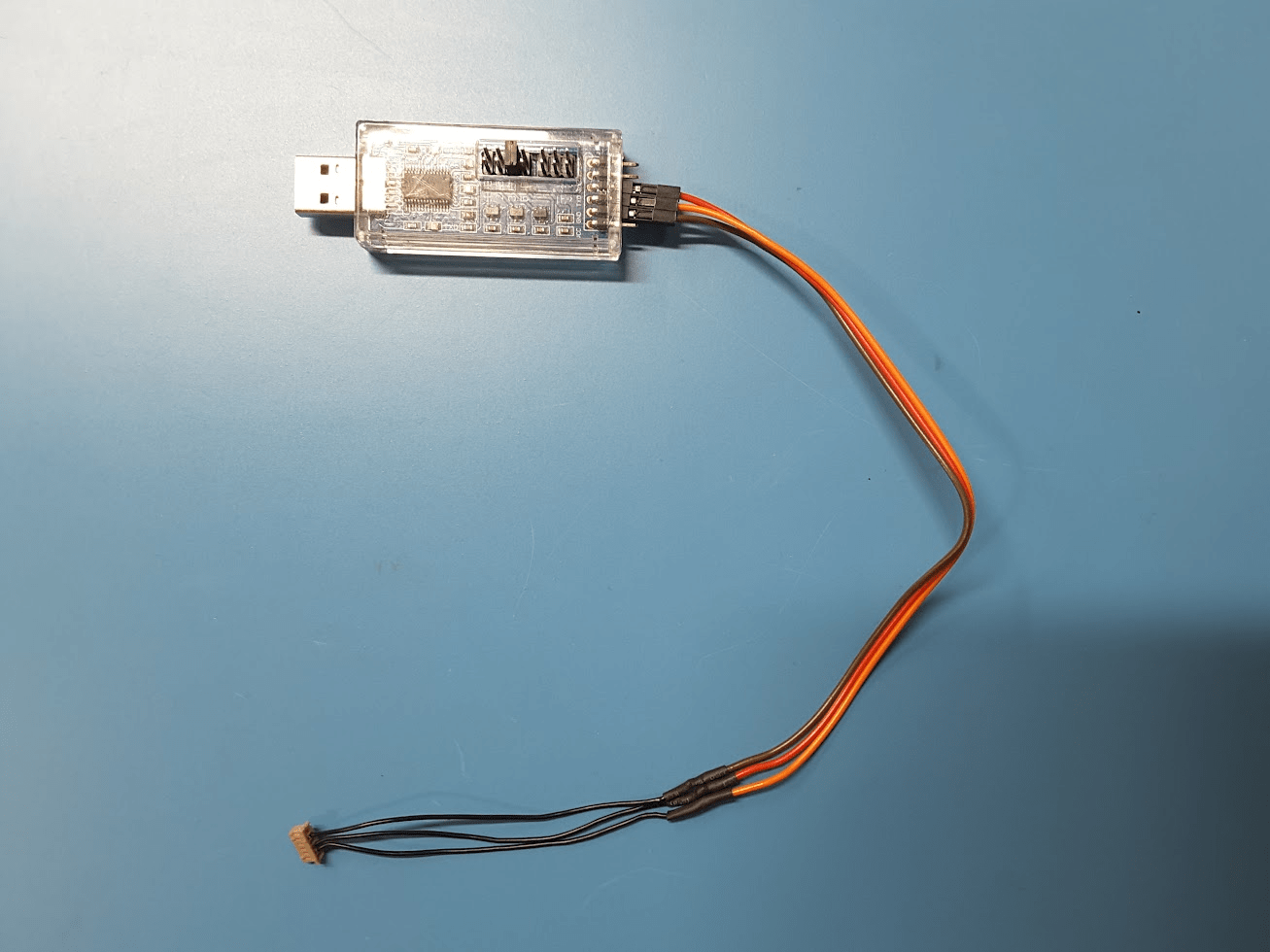
You can interface with a VOXL ESC using your Ubuntu workstation, an USB-2-Serial adapter (such as this adapter), and a serial cable.
Here’s what one USB interface cable looks like:
Serial connector found on ESC
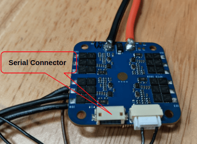
Be cautious when plugging the serial plug into the connector. Be sure no pins are bent out of alignment before inserting the plug and do not bend any pins during the plug in process.
| USB-Serial Adapter | VOXL ESC 6-Pin Serial Connector |
|---|---|
| GND | GND - Pin 5 |
| TXD (3.3v) | RXD - Pin 2 |
| RXD (3.3v) | TXD - Pin 3 |
Part of this cable can be used. VOXL ESC and USB adapter currently tested with 3.3v; if needed, docs say it can support 5v input.
- The USB-Serial adapter comes up as
/dev/ttyUSB0 device.
Run The Tools
Go to the tools directory:
cd voxl-esc/tools
ESC Parameters
Example verify params command:
python2.7 voxl-esc-verify-params.py
Console Output:
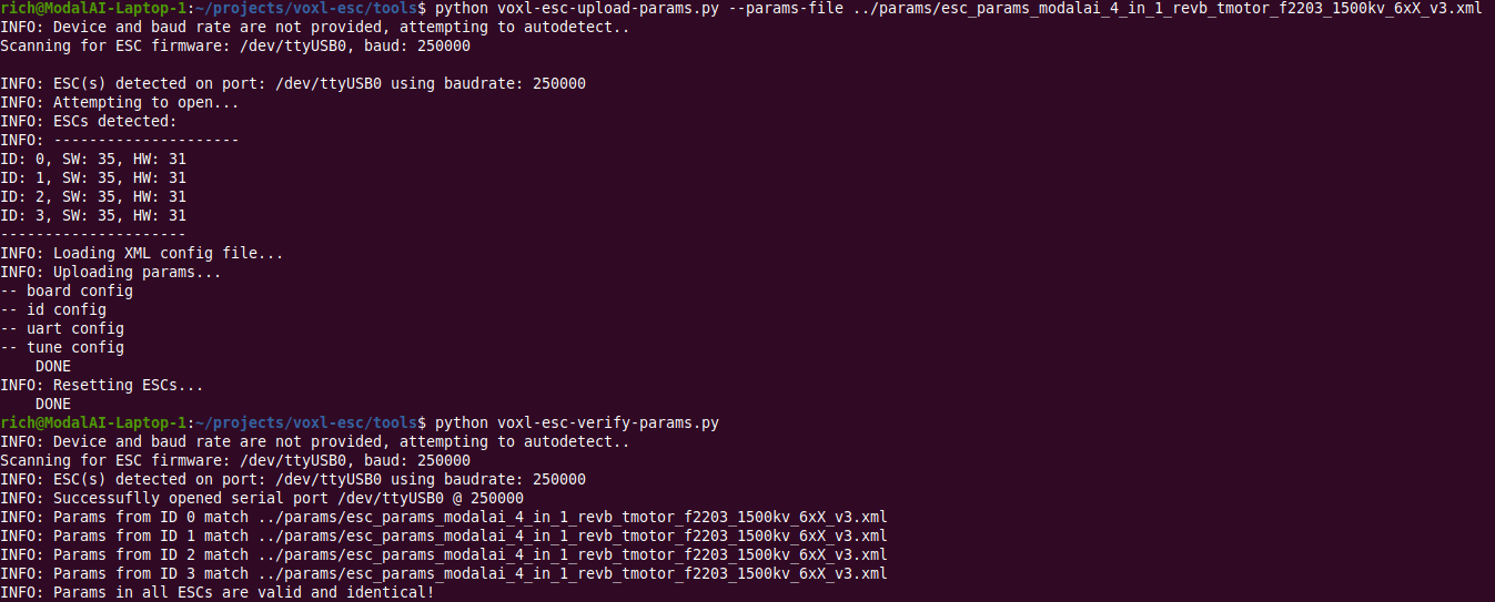
Example upload params command for Seeker:
python2.7 voxl-esc-upload-params.py --params-file ../params/Seeker_V1/Seeker_V1_tmotor_f2203_1500kv_Param_Rev_A.xml
Example upload params command for m500/RB5:
python2.7 voxl-esc-upload-params.py --params-file ../params/RB5_Flight_V1/esc_params_modalai_4_in_1_revb_holybro2216_880_third_kp.xml
Example upload params command for Sentinel:
python2.7 voxl-esc-upload-params.py --params-file ../params/Sentinel_V1/Sentinel_V1_sunnyskyx2216_880kv_10in_mprop_param_Rev_B.xml
Hardware Diagrams
The 4-in-1 ESC board consists of four almost identical copies of a single ESC design.
Single ESC Block Diagram
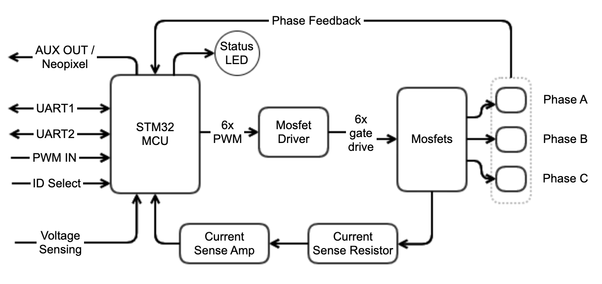
The four ESCs share some components
- 3.3V Voltage regulator
- UART communication lines
- ID_SELECT2 pin (see ID Assignment section)
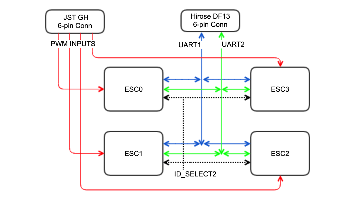
Communication Block Diagram
Connector Information and Pin-outs
UART Connector J2
- Connector on board : Hirose DF13A-6P-1.25H
- Mating connector : DF13-6S-1.25C
- Pre-crimped wires : (Digikey) H4BBT-10112-B8 or similar
- Connector is compatible with VOXL ESC V1, except V2 board has additional UART2 functionality
- 3.3V signals (5.0V input is acceptable)
| Pin > | 1 | 2 | 3 | 4 | 5 | 6 |
|---|---|---|---|---|---|---|
| Function > | VREF_OUT | UART1 RX | UART1 TX | UART2 RX | GND | UART2 TX |
PWM Input Connector J3
- Connector on board : BM06B-GHS-TBT
- Mating connector : GHR-06V-S
- Pre-crimped wires : (Digikey) AGHGH28K305 or similar
- 3.3V signals (5.0V input is acceptable)
| Pin > | 1 | 2 | 3 | 4 | 5 | 6 |
|---|---|---|---|---|---|---|
| Function > | VREF_OUT | PWM_IN0 | PWM_IN1 | PWM_IN2 | PWM_IN3 | GND |
ESC Software Start-up Procedure
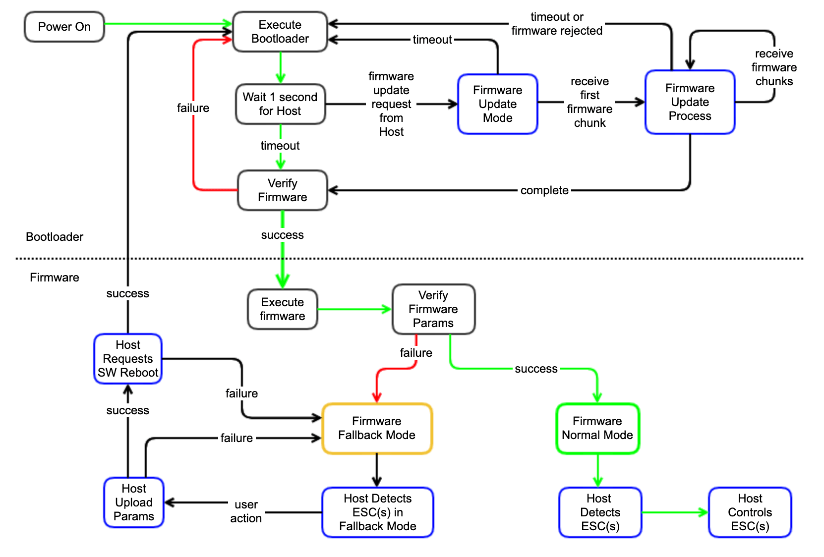
Start-up Error Cases
| Error | Notes |
|---|---|
| Firmware Verification | Verification of the firmware could fail either because the firmware was never installed (fresh board) or the firmware has been corrupted. In this case, the status LED will continuously blink fast (10Hz) and the ESC will remain in bootloader mode indefinitely, waiting for host to install the firmware |
| Firmware Update | Firmware update could be rejected by the Bootloader if incompatible firmware is provided by host. Incompatible firmware is detected before erasing existing firmware, so the old firmware should be retained in this case. Also, firmware update could fail in the middle of the update (loss of power or communication) - in this case the previous firmware would be lost and the ESC would end up without valid firmware. To fix this, simply re-install the firmware. |
| Firmware Params Verification | If firmware parameters are corrupt or were never installed, ESC cannot be used normally. The firmware will enter a fallback mode, where it uses 57600 baud rate for UART communication and waits for host to upload valid parameters. Upon entering such condition, the firmware will blink 10 times with status LED and make a “sad” motor tone to signal the error. To fix this, use ESC Tools to upload valid firmware parameters |
ID Assignment
- Each of the 4 ESCs on the 4-in-1 board has a unique ID (0-7). The ID is used in software for UART communication.
- IDs are hard-wired on the PCB using 3 inputs to each MCU (thus giving 2^3=8 possible IDs). Two of these pins are different for each MCU and third pulled low by default for 0-3 IDs. (third pin is ID_SELECT2 - see Hardware Diagrams section) is shared for all ESCs, and is selectable via resistor (see datasheet, “ID 4-7 Selection Jumper” in Hardware Overview). If pulled high via a resistor, all ESCs will have IDs in range (4-7).
- This allows to easily configure a board (using hardware resistor) for the desired ID range.
- The bootloader and firmware will read the state of all three ID_SELECTx pins and determine their IDs during initialization.
ESC Spin Test
Example command:
python2.7 voxl-esc-spin.py --device /dev/ttyUSB0 --baud-rate 250000 --id 0 --power 15 --timeout 3
The following bash script can be used for production testing. Copy the text and save to a file called test_esc_motors.sh in your preferred work directory.
In test_esc_motor.sh update the DIR variable to your voxl-esc tools installation directory. Update POWER and TIMEOUT per your testing requirements. Update DEVICE only if your USB-to-Serial dongle comes up as a different one on your device.
#!/bin/bash
DIR="/home/rich/projects/voxl-esc"`
DEVICE="/dev/ttyUSB0"
BAUD="250000"
POWER="10"
TIMEOUT="5"
Go to voxl-esc tools directory: cd $DIR/tools/
Use Python 2.7.xx:
for $mot in {0..3}
do
`python voxl-esc-spin.py --device $DEVICE --baud-rate $BAUD --id $mot --power $POWER --timeout $TIMEOUT --skip-prompt True`
done
After you save the file, run the command to make it executable:
chmod +x test_esc_motors.sh
To Run:
./test_esc_motor.sh
Disconnecting ESC plug:
Use caution when unplugging the wire from the ESC. DO NOT pull on the wires as this will cause the cable/plug to break and need repair/replacement. Use your nails or a similar tool (such as a spudger) to grab/pry/pull on the outside edges of the connector. Just be gentle with it.
Take caution to not bend any of the pins on the ESC board
Calibration
Details of how to calibrate the ESCs for high-performance with new battery, motor or propeller configurations can be found here
Other Resources
FAQ
Q: When I apply power, the board continuously flashes the LED very quickly and nothing else happens (not motor tones). What is wrong?
A: If board is in this state, it means it has only bootloader installed but no firmware. Upload appropriate firmware using ESC Tools
Q: When I apply power, the board flashes LED for 1 second, then flashes 10 times more slowly and emits a sad motor tone. What is wrong?
A: Try to use ESC scan feature in ESC Tools. If it detects ESC at 57600, then it means there are no params uploaded. Upload appropriate params using the ESC Tools
Q: When is ESC Calibration Required? A: When switching battery types (from 3S LiPo to 4S LiPo, etc), or when a new type of motor or new type of propeller is used.