Flight Core v2 Connectors
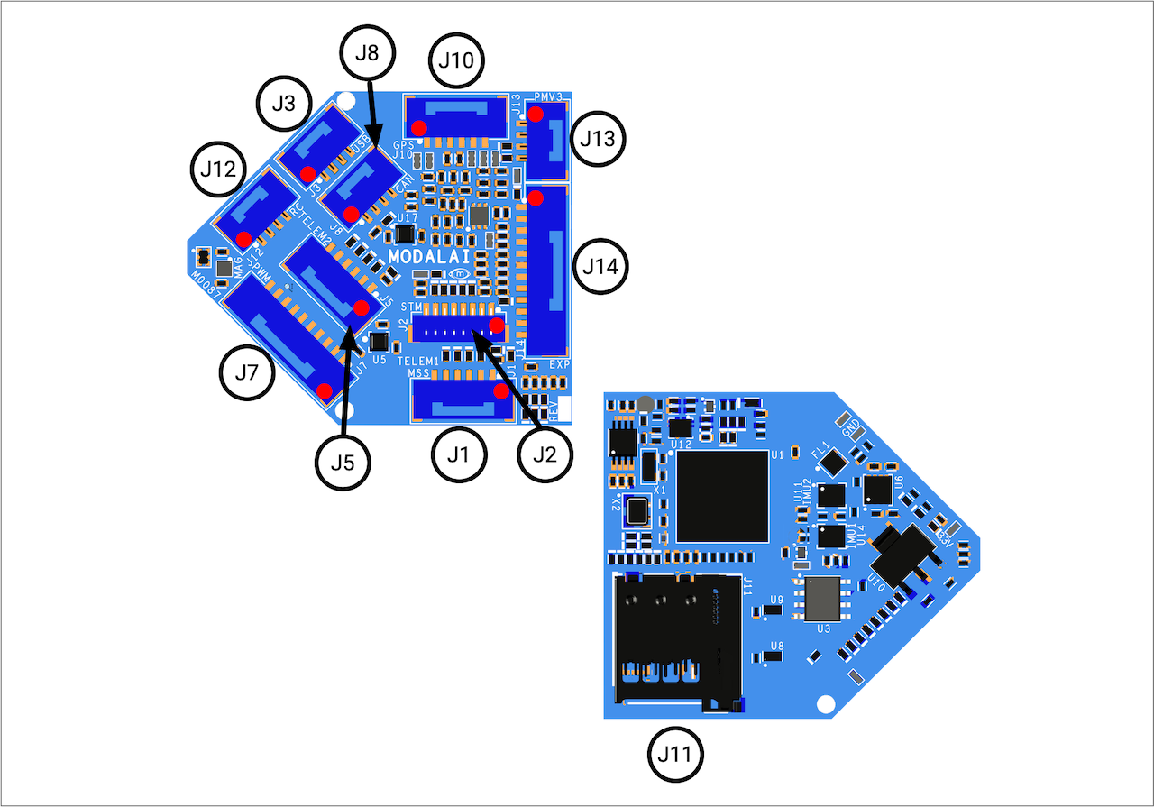
Table of contents
- J1 - TELEM1 / UART7 / VOXL Mavlink Default Port
- J2 - Programming and Debug Console
- J3 - USB Connector
- J5 - TELEM2 / UART5 / ESC Port
- J7 - 8-Channel PWM Output Connector for PWM or DShot ESCs
- J8 - CAN Bus Connector
- J10 - External GPS & Magnetometer Connector
- J11 - Micro SD Card Slot
- J12 - RC input
- J13 - Power Input and VOXL PM Monitoring
- J14 - External SPI/I2C/ADC
J1 - TELEM1 / UART7 / VOXL Mavlink Default Port
Board Connector: BM06B-GHS-TBT
Mating Connector: GHR-06V-S
Notes:
- Default port for VOXL to talk to PX4
- connected to STM32 UART7 through level shifters (74LVCH2T45), in Nuttx it’s
/dev/ttyS6 - Follows DroneCode Telemetry Port signal format
| Pin # | Signal Name |
|---|---|
| 1 | 5P0V (from power-in source) |
| 2 | MSS_UART_4W_FSS_TX, UART TX, 3.3V levels |
| 3 | MSS_UART_4W_FSS_RX, UART RX, 3.3V levels |
| 4 | MSS_UART_4W_FSS_RTS, UART CTS, 3.3V levels, not used by ModalAI generally… |
| 5 | MSS_UART_4W_FSS_CTS, UART RTS, 3.3V levels, not used by ModalAI generally… |
| 6 | GND |
J2 - Programming and Debug Console
Connector: BM08B-SRSS-TB(LF)(SN)
Mating Connector: SHR-08V-S
Notes:
- connected to STM32 USART3
- used for PX4 debug console, can be used for STM32 FW update
- Follows DroneCode Pixhawk Debug Mini connector format on pins 1-6. Pins 7&8 added are extensions.
| Pin # | Signal Name |
|---|---|
| 1 | VREG_3V3 |
| 2 | UART_2W_DEBUG_TX |
| 3 | UART_2W_DEBUG_RX |
| 4 | SWDIO |
| 5 | SWCLK |
| 6 | GND |
| 7 | !RESET |
| 8 | VPP_STM |
J3 - USB Connector
Connector: BM04B-GHS-TBT: BLUE colored connector for easy identification of USB (pending supply chain availability)
Mating Connector: GHR-04V-S
Notes:
- On Flight Core v2, this connector DOES allow for system power for QGC programming modes without a battery. More explanations and limitations are described at the functional description.
| Pin # | Signal Name |
|---|---|
| 1 | USB_VBUS_IN |
| 2 | USB_D_M |
| 3 | USB_D_P |
| 4 | GND |
J5 - TELEM2 / UART5 / ESC Port
Default port to talk to ModalAI UART ESCs
Board Connector: BM06B-GHS-TBT
Mating Connector: GHR-06V-S
Notes:
- connected to STM32 UART5 (ttyS4) directly
- Follows DroneCode Telemetry Port signal format
| Pin # | Signal Name |
|---|---|
| 1 | 5P0V (from power-in source) |
| 2 | TELEM2_FSS_4W_UART_TX, UART TX, 3.3V levels |
| 3 | TELEM2_FSS_4W_UART_RX, UART RX, 3.3V levels |
| 4 | TELEM2_FSS_4W_UART_CTS, UART CTS, 3.3V levels, not used by ModalAI generally… |
| 5 | TELEM2_FSS_4W_UART_RTS, UART RTS, 3.3V levels, not used by ModalAI generally… |
| 6 | GND |
J7 - 8-Channel PWM Output Connector for PWM or DShot ESCs
Connector: BM10B-GHS-TBT
Connector: GHR-10V-S
Notes:
- 5P0V on pin1 is a low power (~100-200ma) reference voltage only, not to provide external power to servoes.
| Pin # | Signal Name |
|---|---|
| 1 | 5P0V (from power-in source) |
| 2 | PWM_CH1 |
| 3 | PWM_CH2 |
| 4 | PWM_CH3 |
| 5 | PWM_CH4 |
| 6 | PWM_CH5 |
| 7 | PWM_CH6 |
| 8 | PWM_CH7 |
| 9 | PWM_CH8 |
| 10 | GND |
J8 - CAN Bus Connector
Connector: BM04B-GHS-TBT
Mating Connector: GHR-04V-S
Notes:
- CAN Transciever is optimzed for CAN FD at 2, 5, and 8Mbps operation
- CAN “Silent” pin (STBY) is controlled by STM32 PD15 pin (default pulled-LOW in hardware)
- Follows DroneCode CAN Port signal format
| Pin # | Signal Name |
|---|---|
| 1 | 5P0V (from power-in source) |
| 2 | CANH* |
| 3 | CANL* |
| 4 | GND |
*CAN signals are compliant with ISO 11898-2:2016 and SAE J2284-1 to SAE J2284-5
J10 - External GPS & Magnetometer Connector
Connector: BM06B-GHS-TBT
Mating Connector: GHR-06V-S
Notes:
- UART connected to STM32 USART1 directly, I2C connected to STM32 I2C1
- I2C pullups provided to 3.3V
- Follows DroneCode Basic GPS Port signal format
| Pin # | Signal Name |
|---|---|
| 1 | 5P0V (from power-in source) |
| 2 | EXT_GPS_UART_2W_TX, 3.3V levels |
| 3 | EXT_GPS_UART_2W_RX, 3.3V levels |
| 4 | EXT_GPS_I2C_SCL, 3.3V levels |
| 5 | EXT_GPS_I2C_SDA, 3.3V levels |
| 6 | GND |
J11 - Micro SD Card Slot
MicroSD slot. Information about supported cards is here: https://dev.px4.io/v1.9.0/en/log/logging.html#sd-cards This socket is a “PUSH-PUSH” format, operates only at 3.3V, and includes PX4 compatable pullups on the SDAT and CMD lines.
J12 - RC input
Connector: BM04B-GHS-TBT: YELLOW colored connector for easy identification of R/C port (pending supply chain availability)
Mating Connector: GHR-04V-S
Notes:
- connected to STM32 USART6 directly
- Pin 1 3.3V controlled by STM32 PH2 output. Power pin is reverse power protected so if a voltage is applied to the output connector, it will not damage the STM.
| Pin # | Signal Name |
|---|---|
| 1 | VREG_3V3_SPEKTRUM (reverse voltage protected) |
| 2 | USART6_TX |
| 3 | SPEKTRUM RX (3.3V), SBus RX (3.3V), USART6_RX |
| 4 | GND |
J13 - Power Input and VOXL PM Monitoring
Connector: BM04B-GHS-TBT: RED colored connector for easy identification of Power In (pending supply chain availability)
Mating Connector: GHR-04V-S
Notes:
- connected to STM32 I2C3 through level shifter TCA9517DGKR
- ModalAI power module includes 5V pullups on I2C bus, 5V pullups on M0087 not installed by default
- Power MUX default input source, even is USBVBUS is present. Refer to functional description page for more info
| Pin # | Signal Name |
|---|---|
| 1 | VDCIN_5V Input |
| 2 | GND |
| 3 | APM_I2C3_SCL_5V |
| 4 | APM_I2C3_SDA_5V |
J14 - External SPI/I2C/ADC
Connector: BM12B-GHS-TBT
Mating Connector: GHR-12V-S
Notes:
- connected to STM32 SPI6, I2C2, ADC1_CH6, ADC1_CH9, ADC1_CH16, ADC1_CH18
- Not Dronecode SPI Port format compliant
| Pin # | Signal Name |
|---|---|
| 1 | VREG_3V3 |
| 2 | SPI6_MISO_EXPANSION (3P3V) |
| 3 | SPI6_MOSI_EXPANSION (3P3V) |
| 4 | SPI6_SCK_EXPANSION (3P3V) |
| 5 | SPI6_CS_EXPANSION_N (3P3V) |
| 6 | I2C2_SDA (3P3V) |
| 7 | I2C2_SCL (3P3V) |
| 8 | ADC1_CH6 (w/inline 10K//10K 50% voltage divider) |
| 9 | ADC1_CH9 (w/inline 10K//10K 50% voltage divider) |
| 10 | ADC1_CH16 (w/inline 10K//10K 50% voltage divider) |
| 11 | ADC1_CH18 (w/inline 10K//10K 50% voltage divider) |
| 12 | GND |