VOXL 2 IO User Guide
Table of contents
Overview
Summary
The VOXL 2 IO board requires a host running PX4 running the px4io module, such as VOXL 2. The IO board provides PWM outputs (8) and expands the native Spektrum RC support by adding S.BUS support (and provides passthrough Spektrum as well).
The IO board is powered from and communicates via VOXL 2’s RC port. The VOXL 2 communicates to the VOXL 2 IO board using a UART connection.
PX4 Version Requirement
ModalAI built PX4 1.12.31 is required for VOXL 2 IO and available in from the dev pkg manager package
Limitations
Supported Mixers and Airframe Setup
Airframe selection via QGroundControl is not supported.
The VOXL 2 IO has validated against quad_x and hex_x airframes only. In the current release, configuring the mixer is done manually by editing the /usr/lib/rfsa/adsp/quad_x_io.main.mix file.
Quad:
R: 4x 10000 10000 10000 0
Hex:
R: 6x 10000 10000 10000 0
UART ESC Compatibility
VOXL 2 IO has not been validated to be used in parallel to the ModalAI UART ESC yet to expose additional PWM channels while also using the ModalAI UART ESC.
PX4 Parameters
The defaults set by voxl-px4-set-default-parameters.config. Ensure you vehicle is configured correctly.
CBRK_IO_SAFETY 22027
PWM_MAIN_MAX   2000
PWM_MAIN_MIN   1060
PWM_MAIN_RATE   400
PWM_MAIN_DISARM 900
Spektrum RC Binding
The Spektrum bind feature invoked via QGroundControl does not work and needs to be ran manually from VOXL2. To enable Spektrum bind:
Connect to VOXL 2’s shell:
adb shell
Run the following commands to put Spektrum RC in bind mode.
px4-qshell px4io safety_on
px4-qshell px4io bind dsmx8
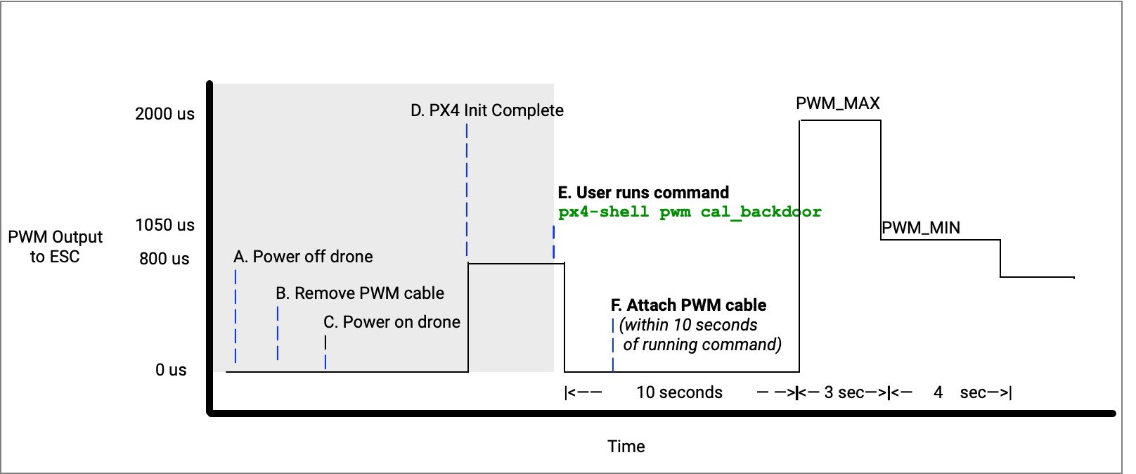
PWM ESC Calibration
NOTE: the following feature is still in beta.
For this process to work, you need to have physical access to J1 (PWM output port).
Use with caution, as this will be setting PWM outputs which could spin motors inadvertently.
REMOVE ALL PROPS. REPEAT: REMOVE ALL PROPS
Using the Sentinel drone with PWM based ESCs as an example:
- Power off the drone
- Remove the PWM cable from VOXL 2 IO connector J1
- Power on the drone
- adb or ssh onto the drone
- get prepared to re-attach the cable (but not yet)
After you do the next step, you have 10 seconds to connect the PWM cable back to J1.
- from the terminal, run
px4-qshell pwm cal_backdoor
Note: you will see an timeout error message, this is OK, for example:
voxl2:/$ px4-qshell pwm cal_backdoor
INFO  [qshell] Send cmd: 'pwm cal_backdoor'
ERROR [qshell] command timed out
ERROR [qshell] Command failed
- re-attach the cable, ESCs will make a short power on jingle
- in 10 seconds, a set of beeps being lasting several seconds
- after the jingles are done, you are done
Here’s the waveform generated over time:
And the same in video, for fun ;)
VOXL 2 Firmware Update
The Firmware Update feature from host to VOXL 2 IO is currently not supported.
Wiring Guides
Host Connection
VOXL 2 as Host (M0054)
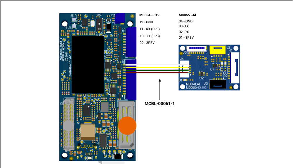
From VOXL2, connect J19 pins 9-12 to VOXL2 IO J4 pins 1-4 as shown here:
| VOXL 2 | VOXL 2 IO |
|---|---|
| J19 Pin 9 - 3P3V | J4 Pin 1 - 3P3V_IO |
| J19 Pin 10 - Host TX | J4 Pin 2 - IO RX |
| J19 Pin 11 - Host RX | J4 Pin 3 - IO TX |
| J19 Pin 12 - GND | J4 Pin 4 - GND |
RB5-Flight as Host (M0052)
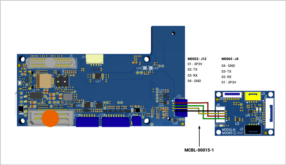
| RB5-Flight | VOXL 2 IO |
|---|---|
| J12 Pin 1 - 3P3V | J4 Pin 1 - 3P3V_IO |
| J12 Pin 2 - Host TX | J4 Pin 2 - IO RX |
| J12 Pin 3 - Host RX | J4 Pin 3 - IO TX |
| J12 Pin 4 - GND | J4 Pin 4 - GND |
RC Connections
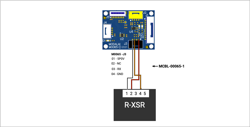
Using S.BUS (FrSky R-XSR)
In the following example, the FrSky R-XSR receiver is being used with MCBL-00065-1:
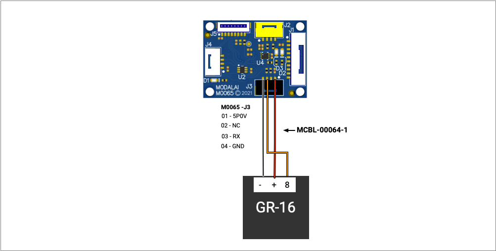
Using S.BUS (Graupner GR-16)
In the following example, the Graupner GR-16 receiver is being used has had it’s channel 8 setup as SBUS with MCBL-00064-1:
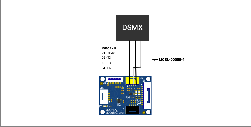
Using Spektrum (DSMX)
In the following example, the Spektrum SMX-SPM9745 receiver is being used with MCBL-00005-1:
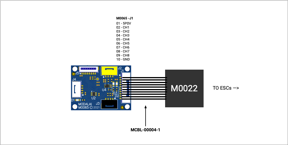
PWM Connection
In the following example, the PWM Breakout Board (MCCA-M0022) and cable (MCBL-00004-1) are used to expose PWM based actuation:
Modes and LED Patterns
The VOXL 2 IO board can be in the following modes accompanied with a unique LED pattern.
- Bootloader Mode
- Application Running in Waiting Mode
- Application Running in Standard Mode
- Firmware update mode
- Communication error mode
Bootloader Mode
For the first 200ms after power on, the VOXL 2 IO is in bootloader mode. The serial firmware update could be performed during this time.
Note: this mode is very short lived an almost not perceptible to the eye.
| VOXL 2 IO LED | State | Meaning |
|---|---|---|
| Green | Solid | Power Good |
| Blue | Off | Application not running |
| Orange | Fast Blink (10Hz) | In bootloader mode |
Application Running in Waiting Mode
When the system is running and communications with VOXL 2 have not started and it is waiting, the following LED pattern can be seen.
| VOXL 2 IO LED | State | Meaning |
|---|---|---|
| Green | Solid | Power Good |
| Blue | Blink Slow (2Hz) | Application running OK |
| Orange | Solid | Warning, waiting for VOXL 2 |
Application Running in Standard Mode
When the system is running, the following LED pattern can be seen.
| VOXL 2 IO LED | State | Meaning |
|---|---|---|
| Green | Solid | Power Good |
| Blue | Blink Slow (2Hz) | Application running OK |
| Orange | Off | No error or warning |
Firmware Update Mode
When the system is in firmware update mode, the following LED pattern can be seen.
| VOXL 2 IO LED | State | Meaning |
|---|---|---|
| Green | Solid | Power Good |
| Blue | Fast Blink (10Hz) | Firmware update in progress |
| Orange | Fast Blink (10Hz) | In bootloader mode |
Communication Error Mode
When communication errors occur, the following LED pattern can be seen.
Note: early RB5 based releases showed this mode when acting as an RC passthrough.
| VOXL 2 IO LED | State | Meaning |
|---|---|---|
| Green | Solid | Power Good |
| Blue | Blink Slow (2Hz) | Communication with VOXL 2 OK |
| Orange | Mediaum Blink (4Hz) | Warning, not getting actuation messages |