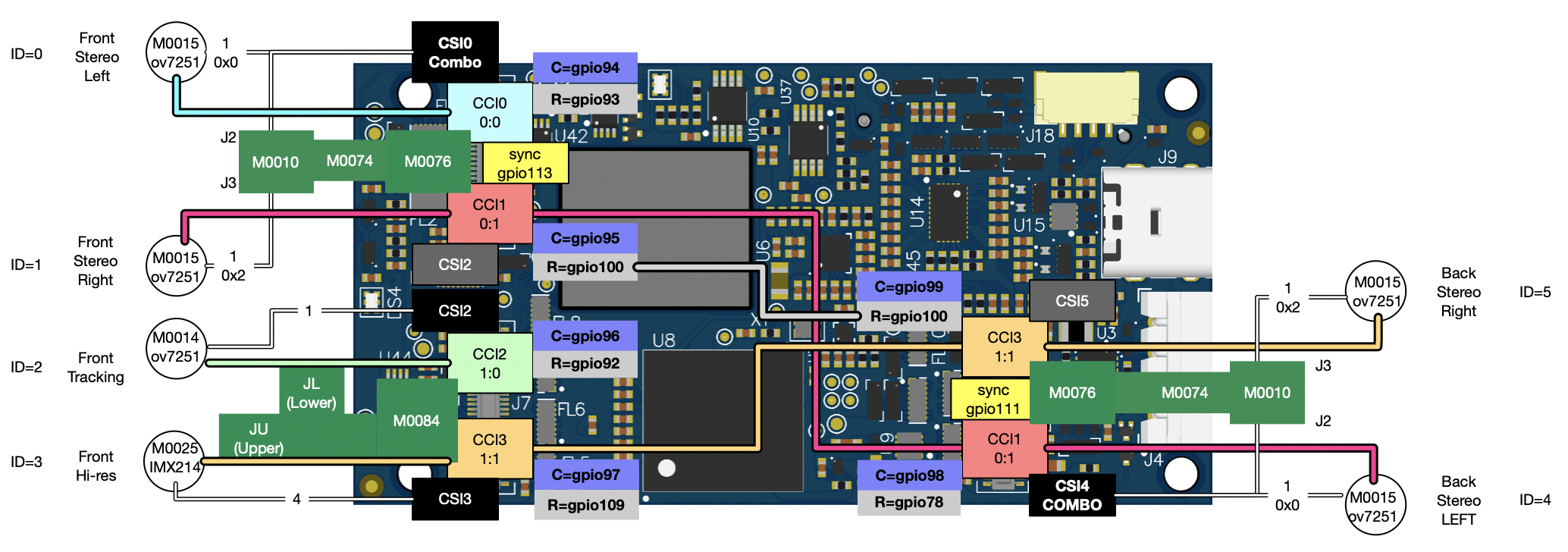
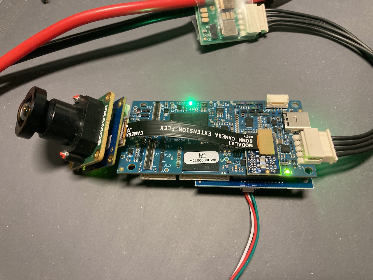
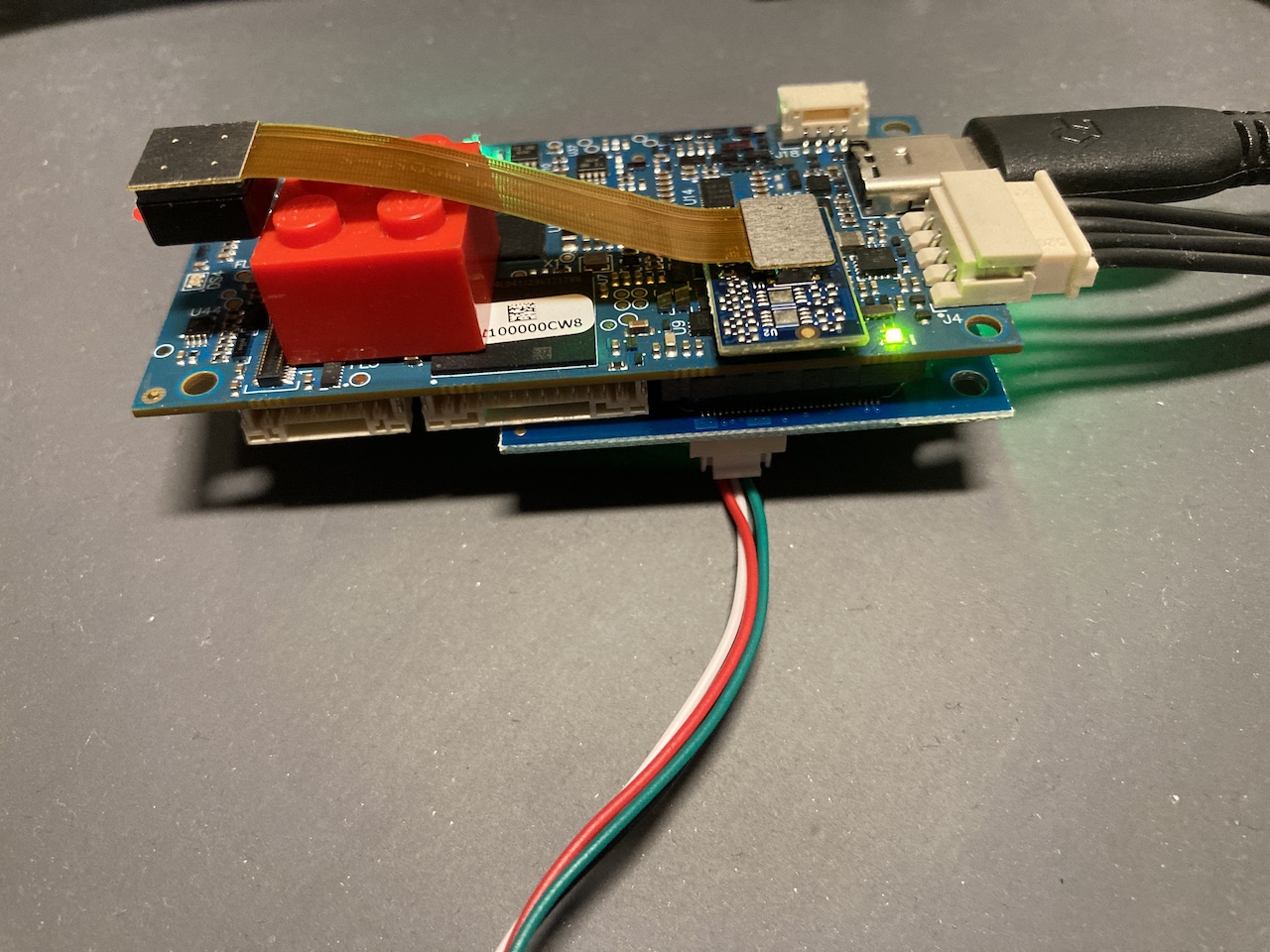
VOXL 2 Camera Configurations
Table of contents
- Overview
- Available Configurations
- Quickstart Video
- How to Configure
- Image Sensor Configurations
- Current Limitations
Overview
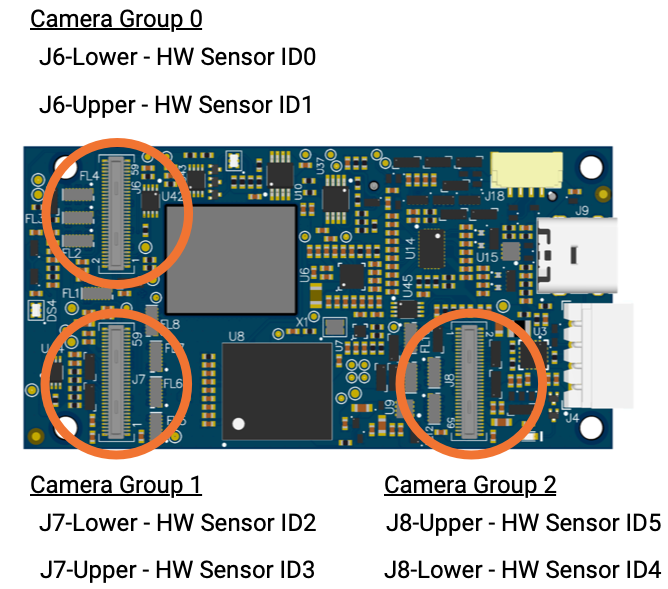
VOXL 2 has 3 camera groups (shown below), where each group has:
- QTY-2 full 4 lane MIPI CSI ports
- CCI and camera control signals
- 8 power rails (from 1.05V up to 5V) for cameras and other sensors
- Dedicated SPI bus
Available Configurations
Platform Release 0.9.5
- SDK 0.9.5
- System Image 1.5.5
Changes
- Added IMX678 support 1920x1080@30, 3840x2160@30
- Enabled more sensor options (see table below)
1.5.5 Supported Sensor Hardware IDs
| HW Sensor ID | Sensor Type | Description | Interposer |
|---|---|---|---|
| 0 | OV7251 M0015 | Stereo | M0010 + M0076 |
| 0 | OV9782 M0113 | Stereo | M0010 + M0076 |
| 0 | PMD TOF M0040 | ToF | M0040 + M0076 |
| HW Sensor ID | Sensor Type | Description | Interposer |
|---|---|---|---|
| 1 | OV7251 M0015 | Stereo | M0010 + M0076 |
| 1 | OV9782 M0113 | Stereo | M0010 + M0076 |
| 1 | PMD TOF M0040 | ToF | NA |
| HW Sensor ID | Sensor Type | Description | Interposer |
|---|---|---|---|
| 2 | OV7251 M0014 | Tracking | M0076, M0084 JL |
| 2 | ov9782 | Tracking | M0076, M0084 JL |
| 2 | PMD TOF M0040 | Depth | M0076, M0084 JL |
| 2 | IMX678 M0061-2 | Hires | M0076, M0084 JL |
| 2 | IMX577/412 M0061-1 | Hires | M0076, M0084 JL |
| 2 | IMX214 M0025-2 | Hires | M0076, M0084 JL |
| HW Sensor ID | Sensor Type | Description | Interposer |
|---|---|---|---|
| 3 | IMX678 M0061-2 | Hires | M0084 JU |
| 3 | IMX577/412 M0061-1 | Hires | M0084 JU |
| 3 | IMX214 M0025-2 | Hires | M0084 JU |
| 3 | PMD TOF M0040 | ToF | M0084 JU |
| HW Sensor ID | Sensor Type | Description | Interposer |
|---|---|---|---|
| 4 | OV7251 M0015 | Stereo | M0010 + M0076 |
| 4 | OV9782 M0113 | Stereo | M0010 + M0076 |
| 4 | PMD TOF M0040 | ToF | M0040 + M0076 |
| 4 | IMX678 M0061-2 | Hires | M0076, M0084 JL |
| 4 | IMX577/412 M0061-1 | Hires | M0076, M0084 JL |
| 4 | IMX214 M0025-2 | Hires | M0076, M0084 JL |
| HW Sensor ID | Sensor Type | Description | Interposer |
|---|---|---|---|
| 5 | OV7251 M0015 | Stereo | M0010 + M0076 |
| 5 | OV9782 M0113 | Stereo | M0010 + M0076 |
| 5 | PMD TOF M0040 | ToF | NA |
| 5 | IMX678 M0061-2 | Hires (alt address 0x20) | M0076, M0084 JL |
1.5.5 Supported Sensor Settings
Some sensors may list additional capabilities when probed from software. Below are what we’ve tested against, other settings may have unexpected results.
| Sensor | Sensor Type | Resolution @ FPS |
|---|---|---|
| IMX678 M0061-2 | Hires | 3840x2160 @ 30 1920x1080 @ 30 |
| IMX412/577 M0061-1 | Hires | 1920x1080 @ 30 |
| IMX214 M0025-2 | Hires | 4096 x 2160 @ 30 3840x2160 @ 30 2048x1536 @ 30 1920 x 1080 @ 30 1280 x 720 @ 30 1024 x 768 @ 30 640 x 480 @ 30 |
| PMD TOF M0040 | ToF | 224 x 1557 @ 5 |
| OV7251 M0014 | Tracking Config | 640x480 @ 30 |
| OV7251 M0015 | Stereo Config Left | 640x480 @ 30 |
| OV7251 M0015 | Stereo Config Right | 640x480 @ 30 |
| ov9782 | Tracking Config | 1280x800 @ 30 |
| OV9782 M0113 | Stereo Config Left | 1280x800 @ 30 |
| OV9782 M0113 | Stereo Config Right | 1280x800 @ 30 |
Platform Release 0.9
- SDK 0.9
- System Image 1.4.1
1.4.1 Supported Sensor Hardware IDs
1.4.1 Supported Sensor Settings
| Sensor | Sensor Type | Resolution @ FPS |
|---|---|---|
| IMX214 M0025-2 | Hires | 4096 x 2160 @ 30 3840x2160 @ 30 2048x1536 @ 30 1920 x 1080 @ 30 1280 x 720 @ 30 1024 x 768 @ 30 640 x 480 @ 30 |
| IMX412/577 M0061-1 | Hires Config | 1920x1080 @ 30 |
| PMD TOF M0040 | ToF | 224 x 1557 @ 5 |
| OV7251 M0014 | Tracking Config | 640x480 @ 30 |
| OV7251 M0015 | Stereo Config Left | 640x480 @ 30 |
| OV7251 M0015 | Stereo Config Right | 640x480 @ 30 |
| ov9782 | Tracking Config | 1280x800 @ 30 |
| OV9782 M0113 | Stereo Config Left | 1280x800 @ 30 |
| OV9782 M0113 | Stereo Config Right | 1280x800 @ 30 |
Quickstart Video
The following video demonstrates setting up the image sensors for the “C11” VOXL 2 development kit:
How to Configure
VOXL 2 ships with the VOXL SDK, which has the voxl-configure-cameras command.
Image Sensor Configurations
C11 - Front Stereo, Rear Stereo, Hires, and Tracking
![]()
| Sensor ID | Sensor Type | Notes | Usage |
|---|---|---|---|
| 0 | OV7251 M0015 | Fsync in0 | Front stereo |
| 1 | OV7251 M0015 | Fsync out0 | Front stereo |
| 2 | ov7251 | Tracking | |
| 3 | imx214, imx412 | Hires | |
| 4 | OV7251 M0015 | Fsync in1 | Rear stereo |
| 5 | OV7251 M0015 | Fsync out1 | Rear stereo |
C3 - Front Stereo, Hires, and Tracking
![]()
| Sensor ID | Sensor Type | Notes | Usage |
|---|---|---|---|
| 0 | OV7251 M0015 | Fsync in0 | Front stereo |
| 1 | OV7251 M0015 | Fsync out0 | Front stereo |
| 2 | ov7251 | Tracking | |
| 3 | imx214, imx412 | Hires |
C10 - Front Stereo Only
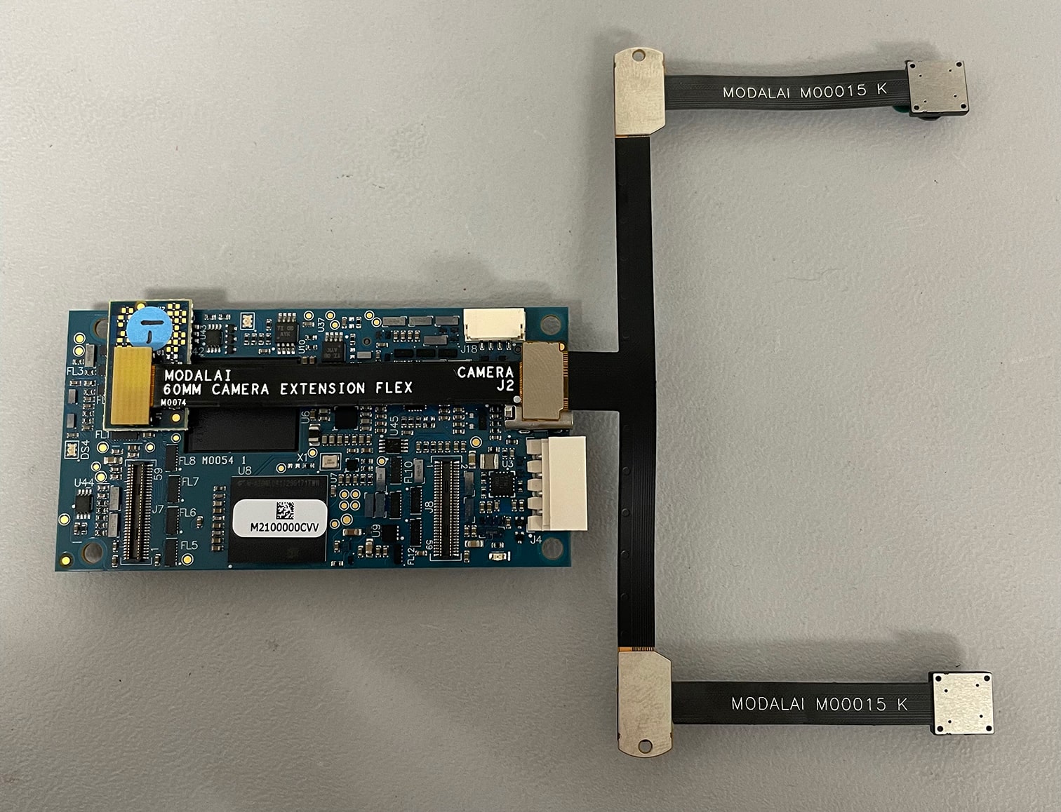
C4 - Tracking and Hires Only
![]()
| Sensor ID | Sensor Type | Notes | Usage |
|---|---|---|---|
| 0 | ov7251 | Tracking | |
| 1 | imx214, imx412 | Hires |
C6 - Hires + ToF + Tracking
Available starting with Platform Release 0.9, sys img 1.4.1.
HW Setup
![]()
| Sensor ID | Sensor Type | Notes | Usage |
|---|---|---|---|
| 0 | PMD TOF M0040 | Depth 0 | |
| 1 | ov7251 | Tracking | |
| 2 | imx214, imx412 | Hires |
C8 - Hires Only
Available starting with Platform Release 0.9.5, sys img 1.5.3.
M0061-2 based IMX678, on M0054 J8 (no other camera location for IMX678 is supported in 1.5.3, must be J8).
Shown here, the M0076 interposer plugs into M0054 J8. The M0074 flex then connects to the M0061-2 backpack for the IMX678 module.
M0025-2 based IMX214, on M0054 J8.
SW Setup
voxl2:/$ voxl-configure-cameras 8
C9 - Time of Flight (ToF) Only
Available starting with Platform Release 0.9, sys img 1.4.1.
HW Setup
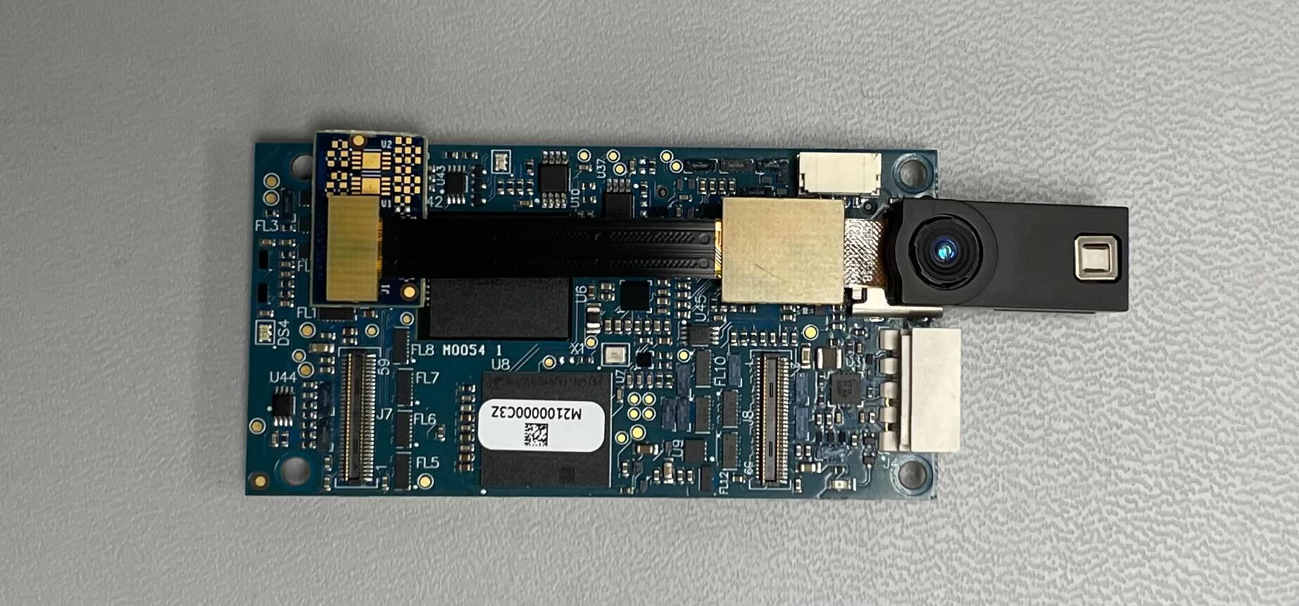
| Sensor ID | Sensor Type | Notes | Usage |
|---|---|---|---|
| 0 | PMD TOF M0040 | Depth 0 |
SW Setup
voxl2:/$ voxl-configure-cameras 9
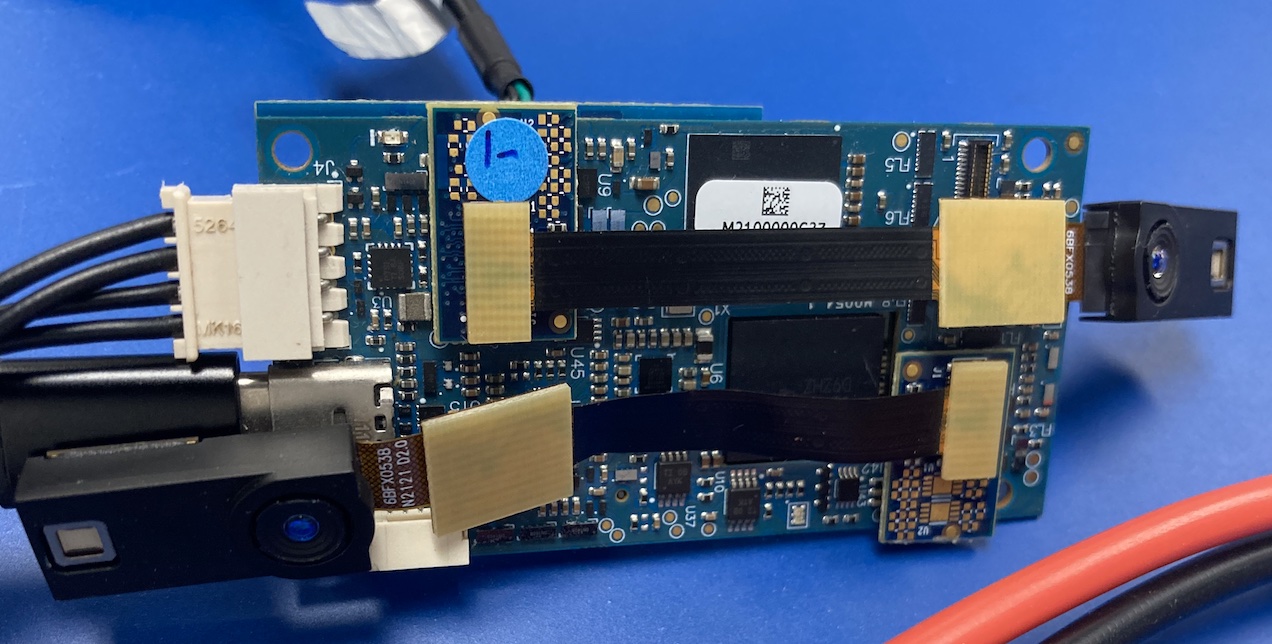
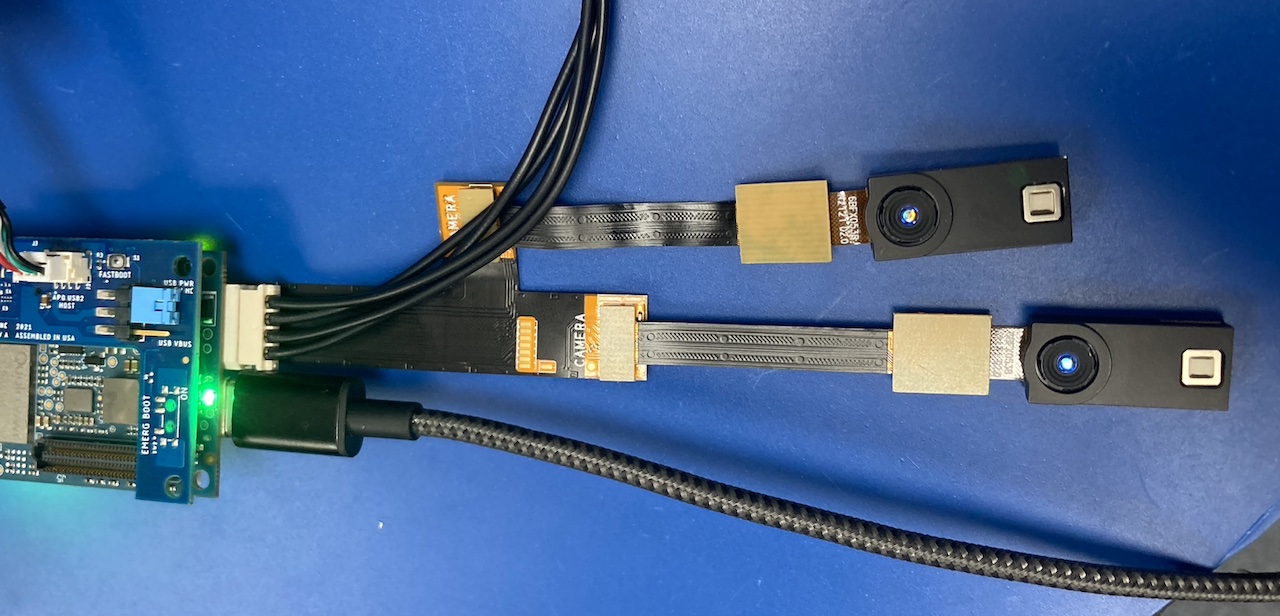
CX - Two Time of Flights (ToF)
Available starting with Platform Release 0.9, sys img 1.4.1.
HW Setup
Using the M0076-1 interposers on J6 and J8 as examples:
Using the M0084-1 dual camera adapter (“y-flex”) on J8 as example:
SW Setup
NA
Current Limitations
- As a means to allow coexistence of OV7251 sensors on
CCI3, we are not resetting sensors when they normally should per Qualcomm, to prevent the sensors losing a runtime address swap. This modification is in the kernel, dmesg showsMODALAI HACKwhere it’s happening. - Sensor ID 1 and Sensor ID 5 share a reset line (gpio100), no specific known defects but an area to watch out.
- Sensor indicies assume all six sensors are in place and will shift when not fully populated.
- All camera AVDD rails in this configuration are left on always (2P8VDC) as they’re shared
